
— This page was written to describe the early design and build process to my grandson, so he will know, and , before I forget it all…
(here is a YouTube link of the nearly completed layout (lot of details to add) – the write-up follows)

Fall of 2018…I am about a year into the build and mostly have just to design, lay out and build the structure kits to do the town, so it is probably a good place to start to try and explain it all…
The basic layout is based upon a design I found long ago in one of Atlas RR’s books – it is called their N-17 and probably you can still find it online even when you go to read this many years later! I built most of the layout over 30 years ago but never finished and wound up selling to a guy to use as a Christmas present for his son. I mostly wanted to test myself to see if I could master the many techniques it takes to pull one of these things together…I did a pretty good job back then…
When you came along, I thought it would be fun to try it again, but with some extras, so you could play with it and have some fun yourself. So, here goes the recap!
Layout overview…

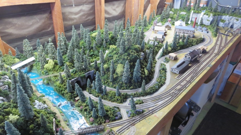
As I said, the layout is based on N-17, but I wanted to expand that one a bit to allow more room to do landscaping. So, I added the section to the left of the main river. It allowed the big mountain area, the meadow (one of your Gramma and my favorite environments when we travel into the mountains), the pond, the flume, the lumber yard and the helix that is inside the mountain.
I thought at some point the layout might wind up inside the house, so rather than have one long basic structure, I split it up so that the new left-hand side could be separated from the main layout to facilitate moving…if that happens, I would have to cut down through the main river and redo it afterwards – a real pain, but doable.

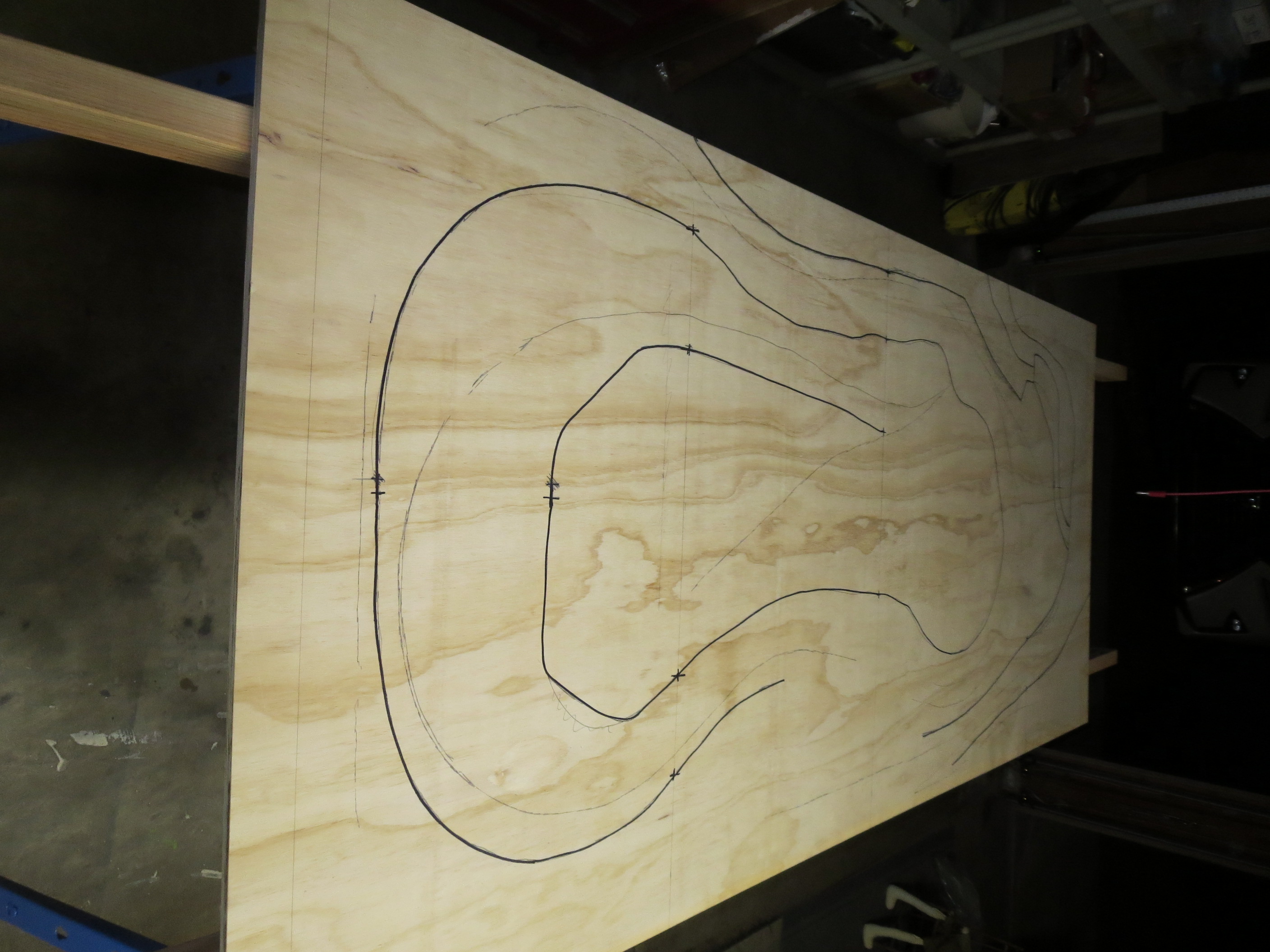
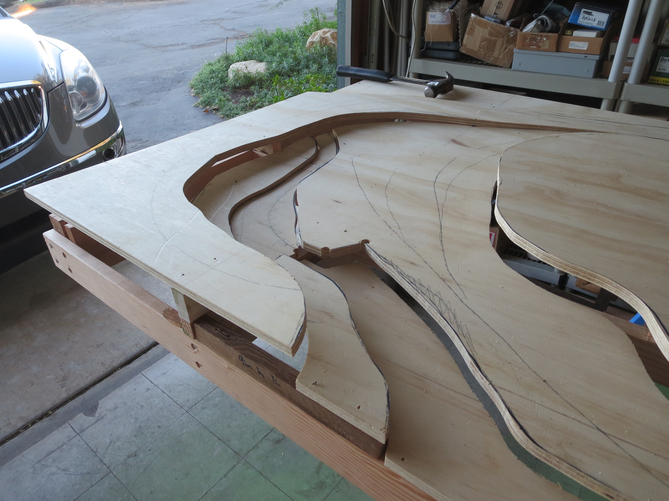
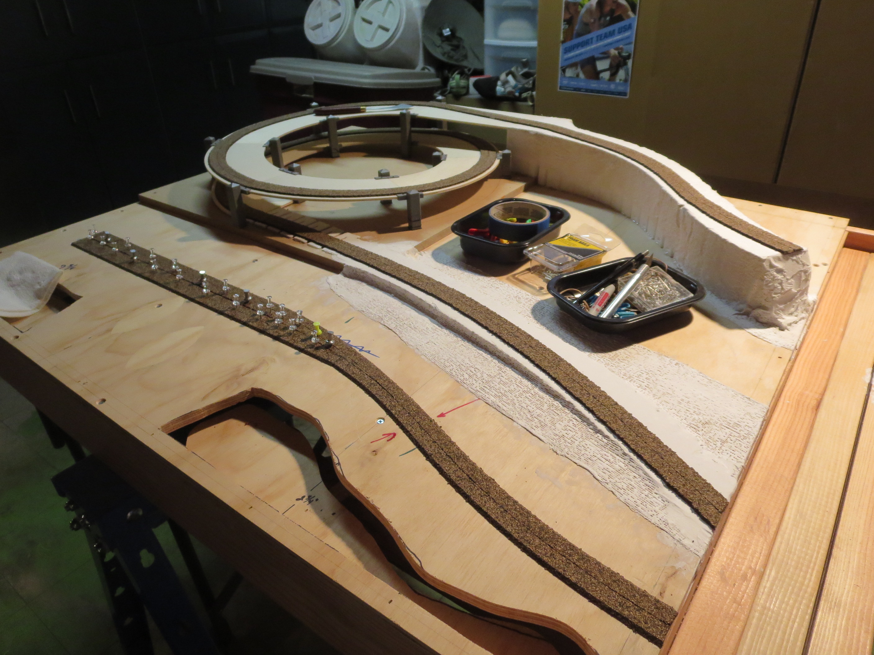
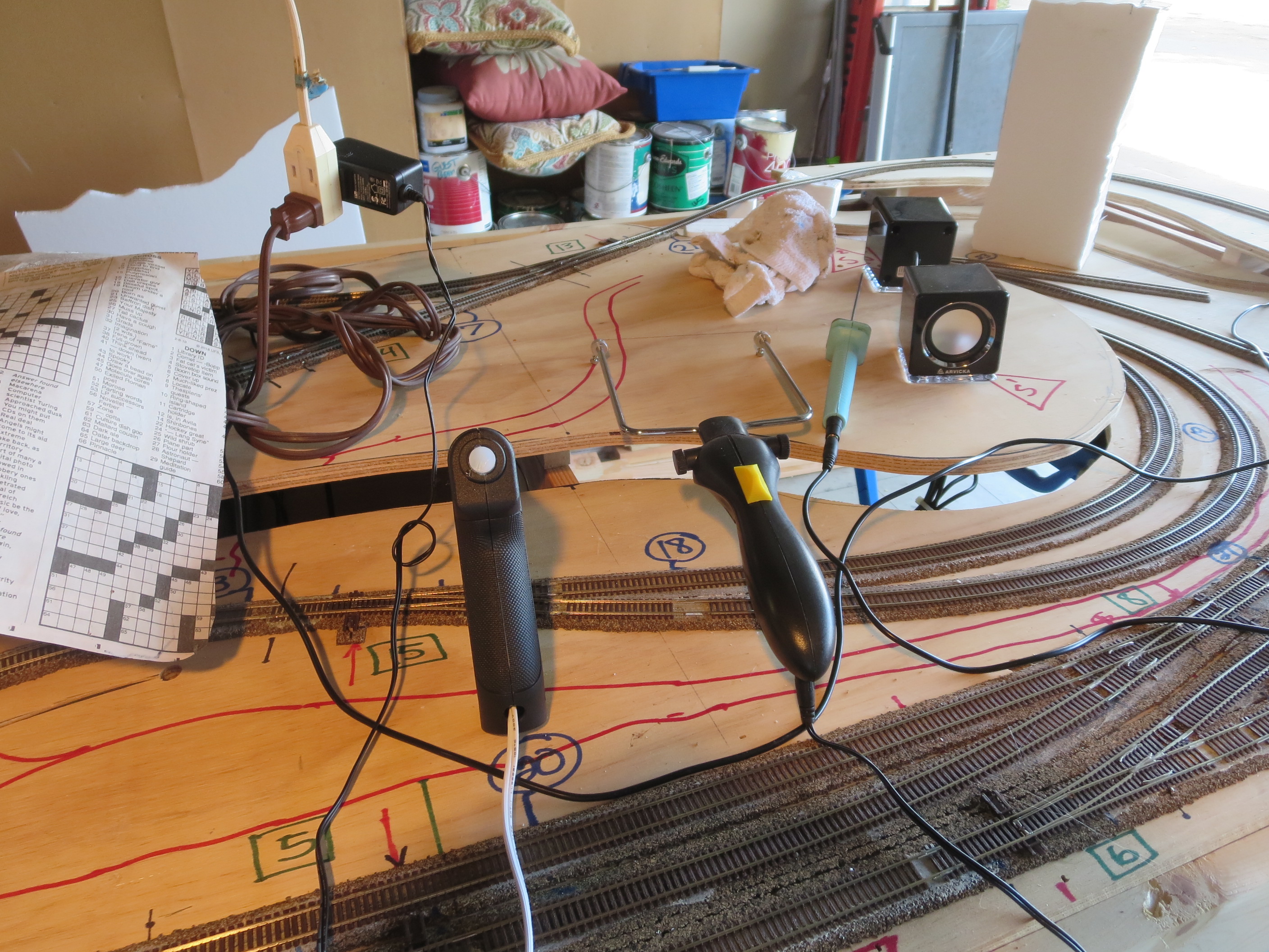
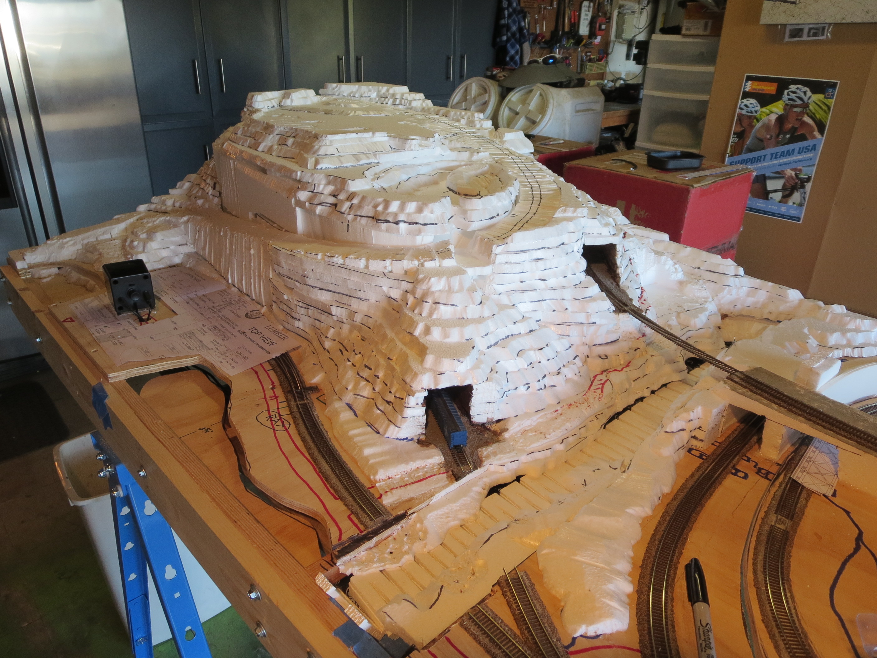
As you can see in the picture above, much of the elevation change is accomplished by cutting and propping up sections of the surface plywood – this is all patterned in the Atlas RR book layout and works well. However, since there was going to be so much terrain change for the new section, I wanted to try something different. The last time I built the layout, I used a construction technique for the terra forming where I shaped a hill or rise with window screen and plaster – this time I decided to try building up layers of foam board. It is much lighter and allows a bit more creativity in terracing the terrain.
The Benchwork…

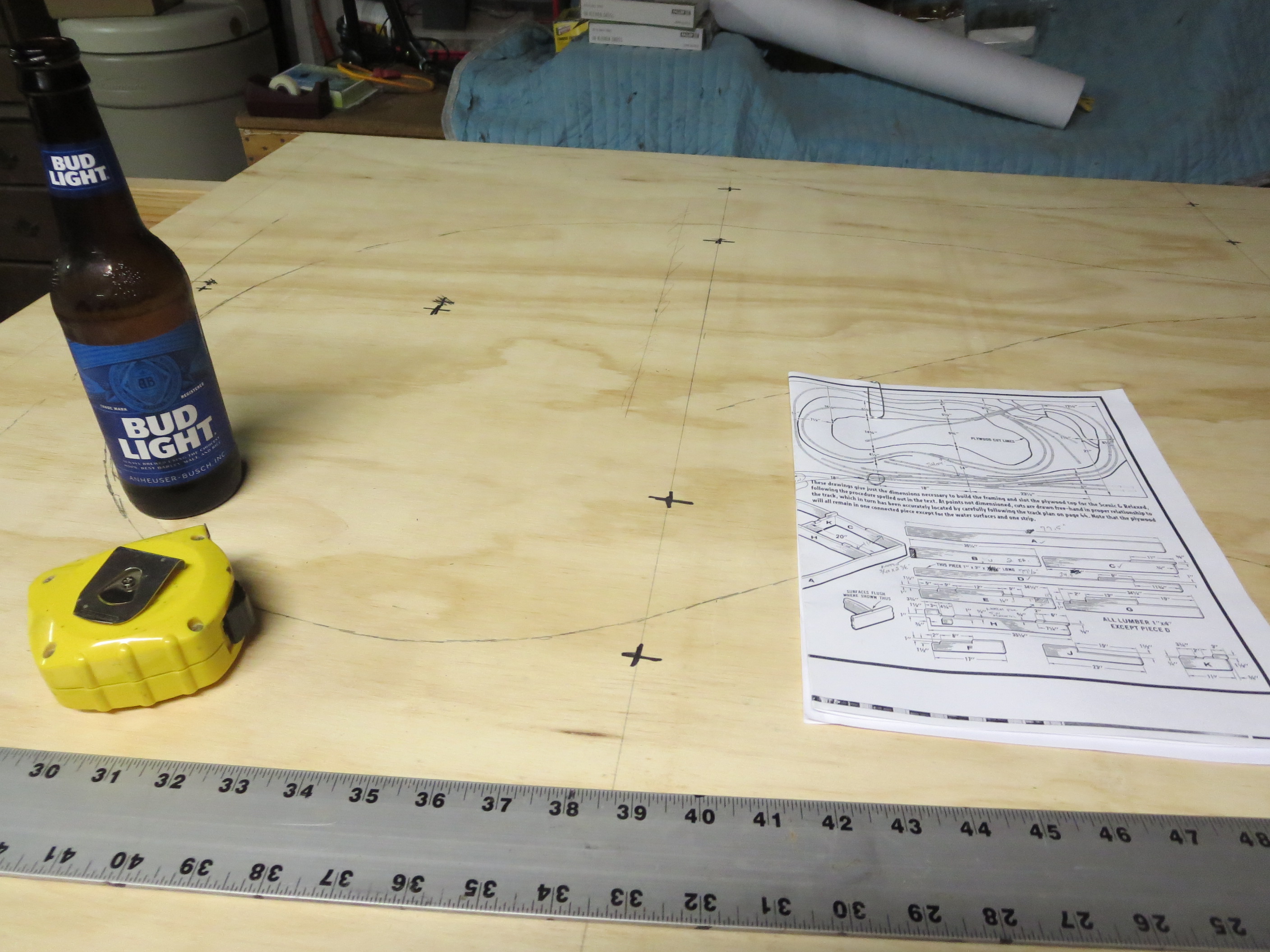
After doing a bunch of work designing the layout “on paper” (some sketching and some software), I bought wood supplies, printed out the basic track layout and transferred it onto the plywood. Then I grabbed your Dad to help get the board work started.

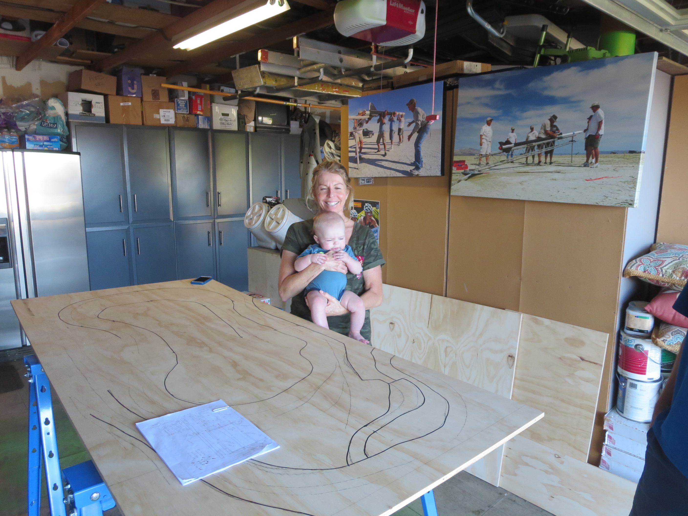
You and Gramma helped by supervising!
The Track…
Once the board work was finished, I could start laying out the track itself. I chose an N-gauge layout because it allows a lot of train in a small area. The most popular modelling gauge is called HO, and it is twice as big, but that means that our 3’ x 12’ layout would take up a 6’ by 24’ area to have the same amount of features! I barely convinced Gramma to allow the N-gauge layout – no way could I steal the area needed for HO!! The downside is that things can get a bit tedious at times since it as all so small and fragile.

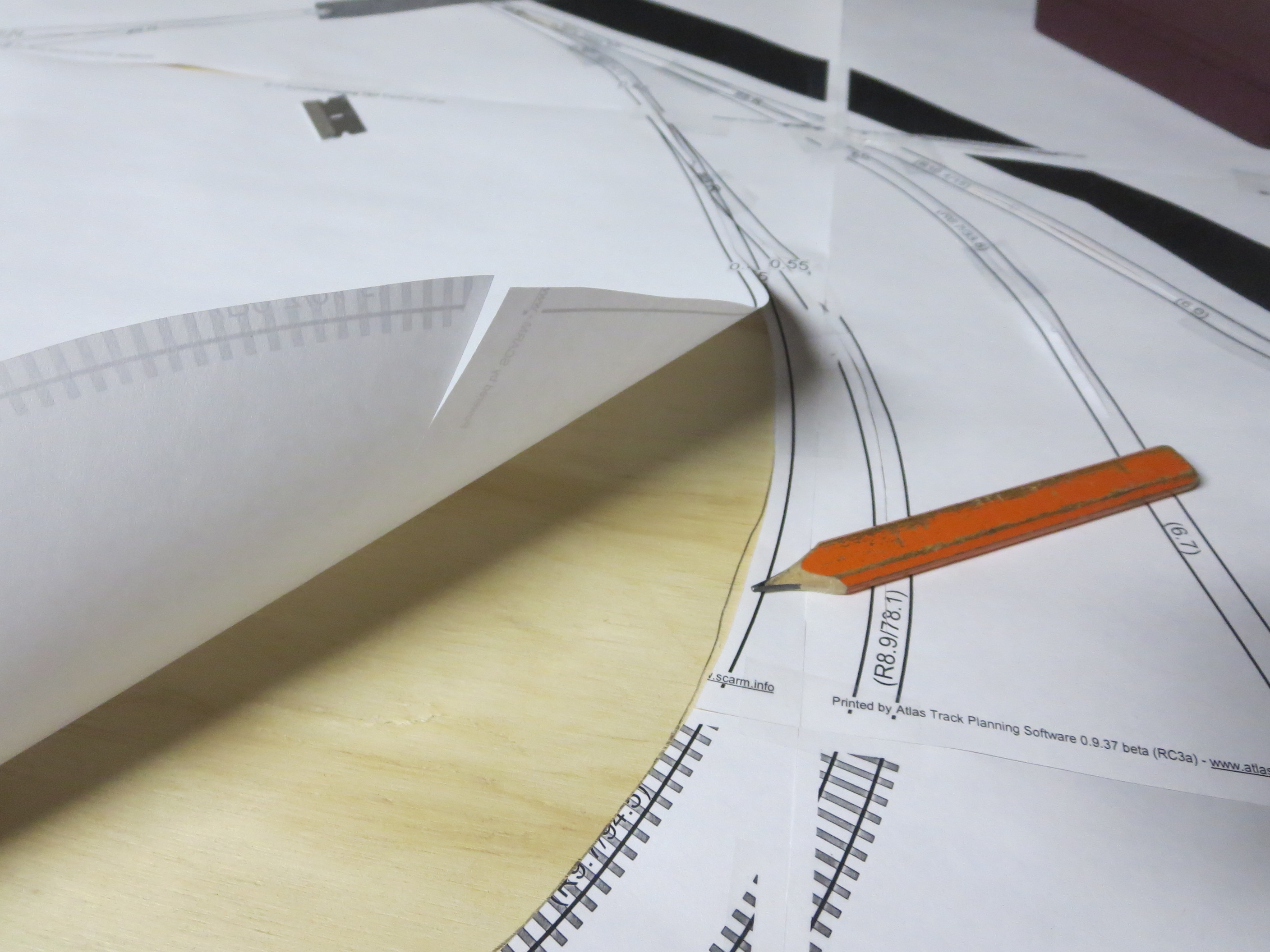
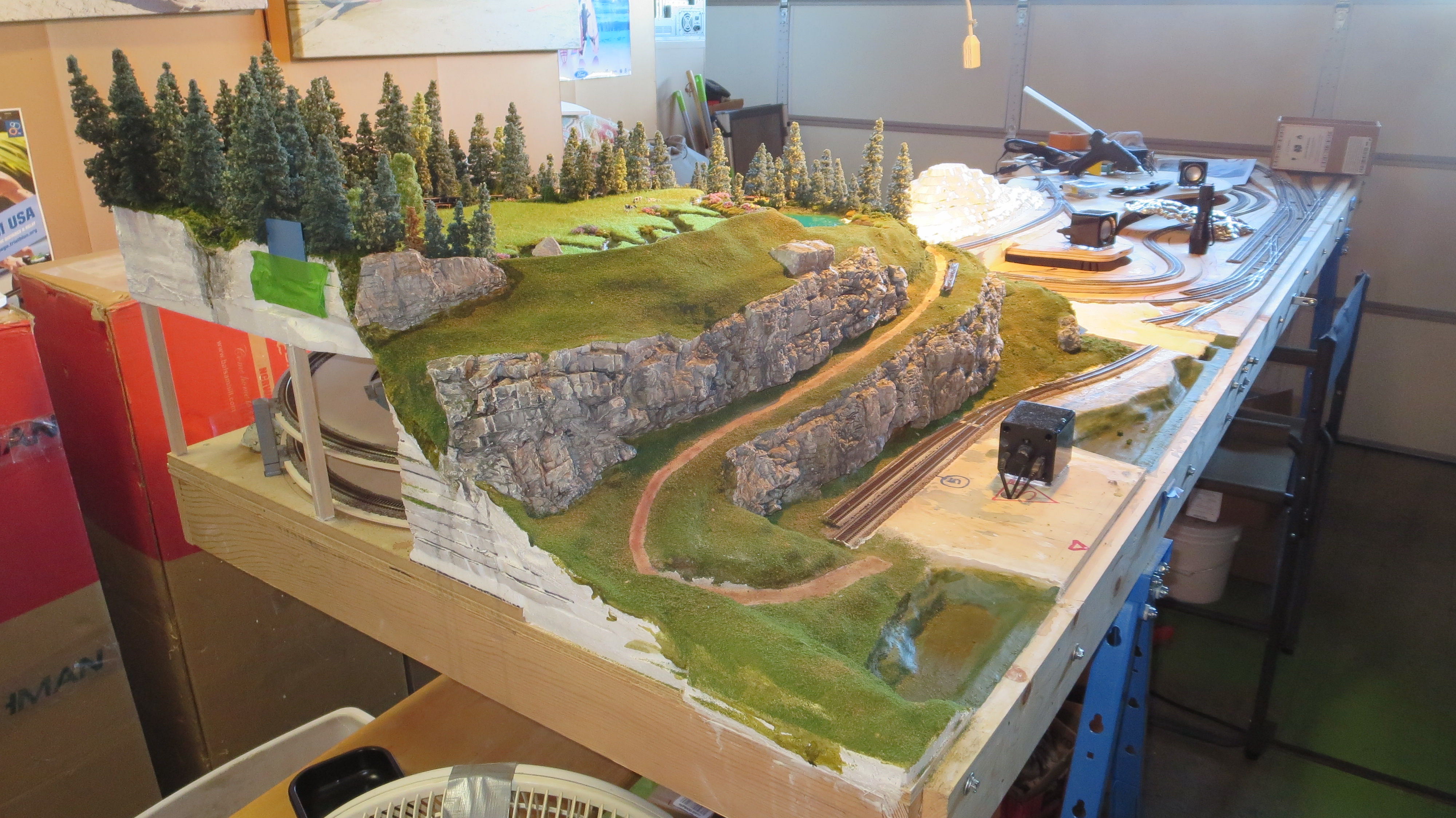
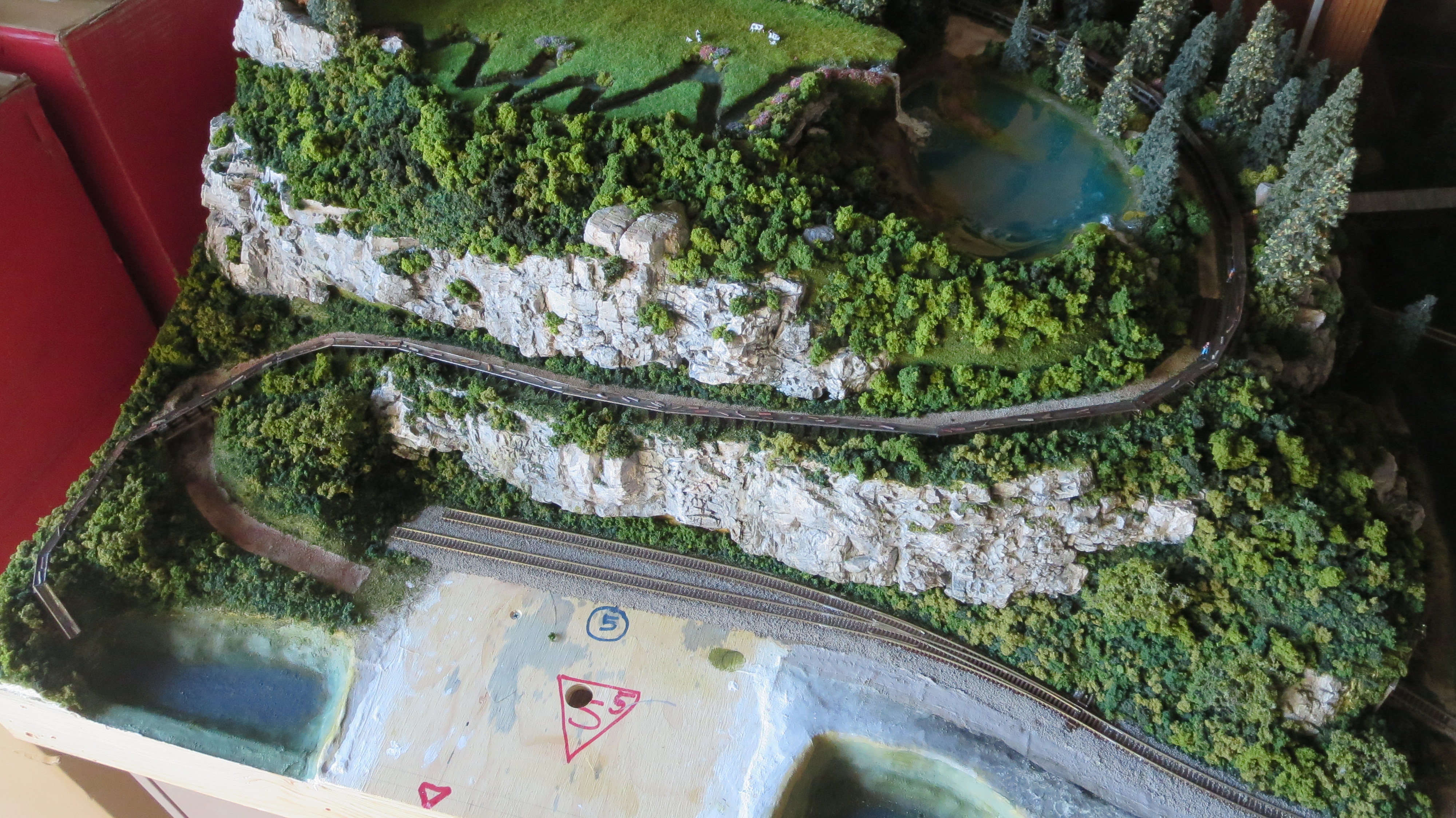
You can see in this picture both the raised wood method and the start of the foam method (foam ramp for track at the upper right). I was fortunate in that over the 30+ years since the prior build, they have developed so much stuff to help get the layout built. It was a real help to be able to create the track on the computer, then print out the results in 1:1 scale, place the printouts on the top surface and trace the track lines.
Elevations The area here closest is called cookie-cutter; the plans for how to do the wood structure underneath in order to prop up the cut plywood is all contained in the Atlas book – basically, you build the understructure with 1”x3”’s and 1”x4”’s, then use a sabre saw to cut the plywood top, then set the top on the under-structure which causes it to separate into the various elevations. All of the area on the other side of the river (left) using the foam method came out of my head – rough track layout to include the inside the mountain helix and then the detailed elevation stuff with the foam, I created as I built it.
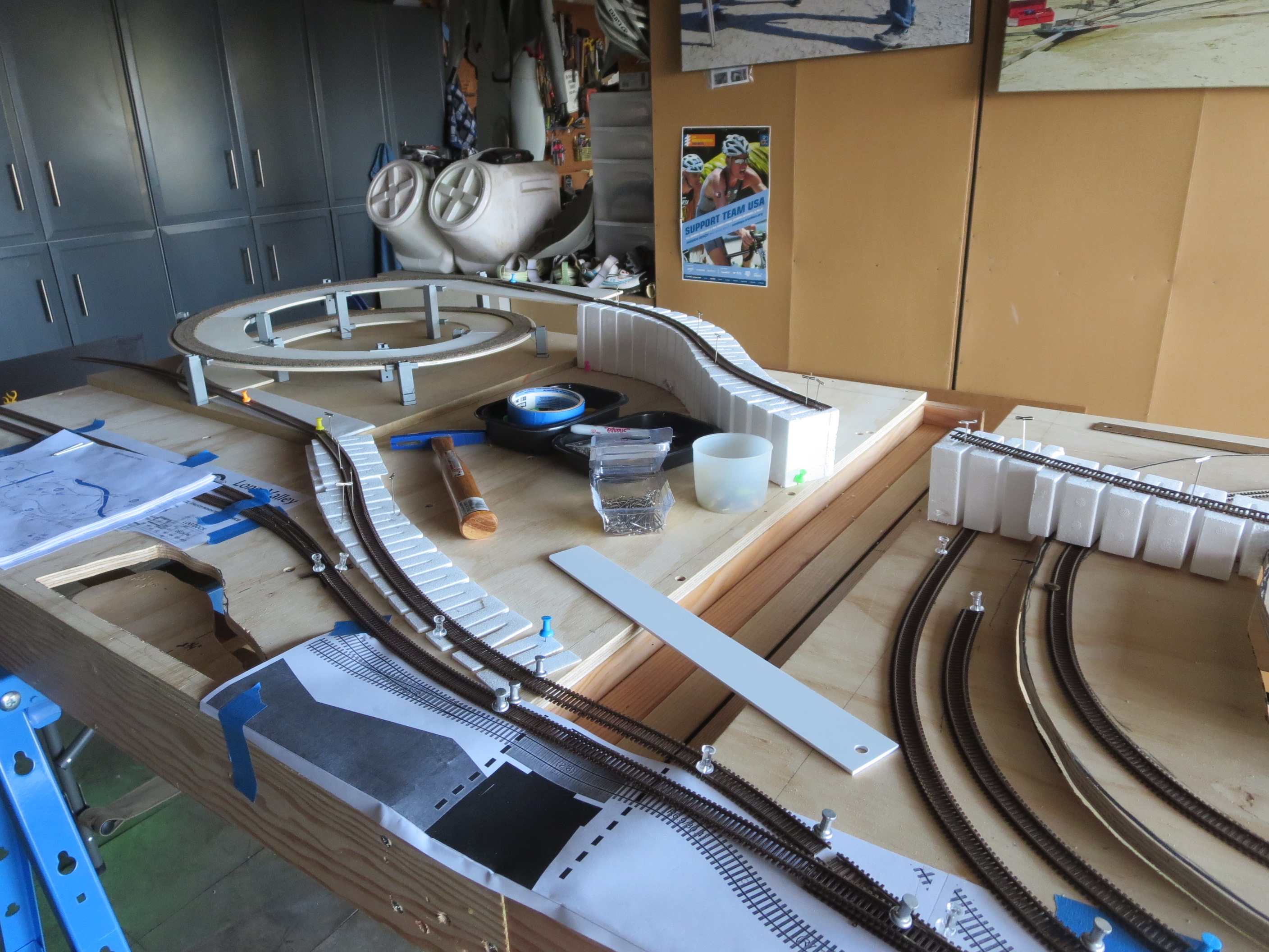
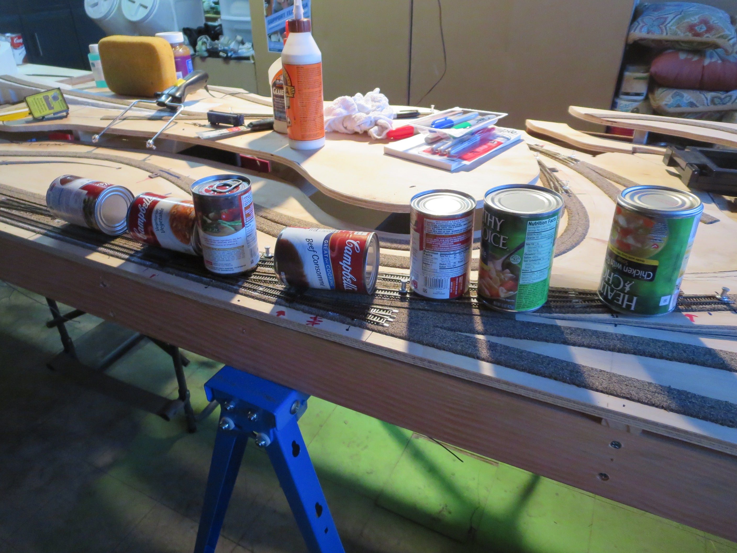
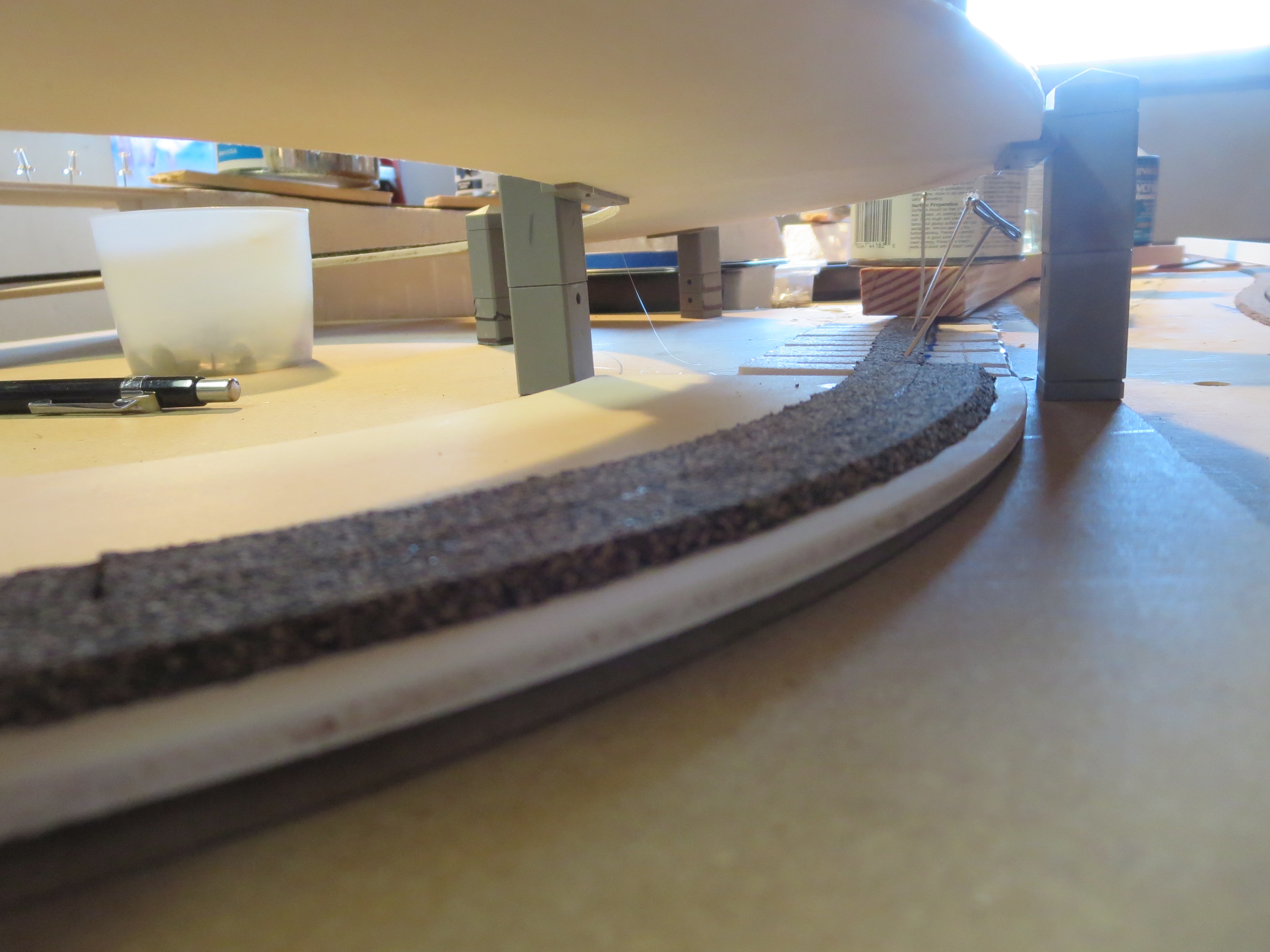
Roadbed and track After I had traced the layout onto the plywood, I laid out the track itself onto the plywood top just to be sure it all went together OK. Then I glued cork roadbed over the traces with white glue (like Elmer’s) to provide a cushion/sound deadening for the track, as well as to bring it up a bit from the surface so that when I ballasted it later on, it would look more realistic. Once I had the cork down, I glued the track into place using latex caulk. It was so nice to have the internet available to do research this time around – you can gain the experiences of many others in a short time!
Helix The helix is used to rapidly elevate the track up or down in a small space. The train engines are only so powerful, so you have to avoid steep grades or the trains will not be able to climb.
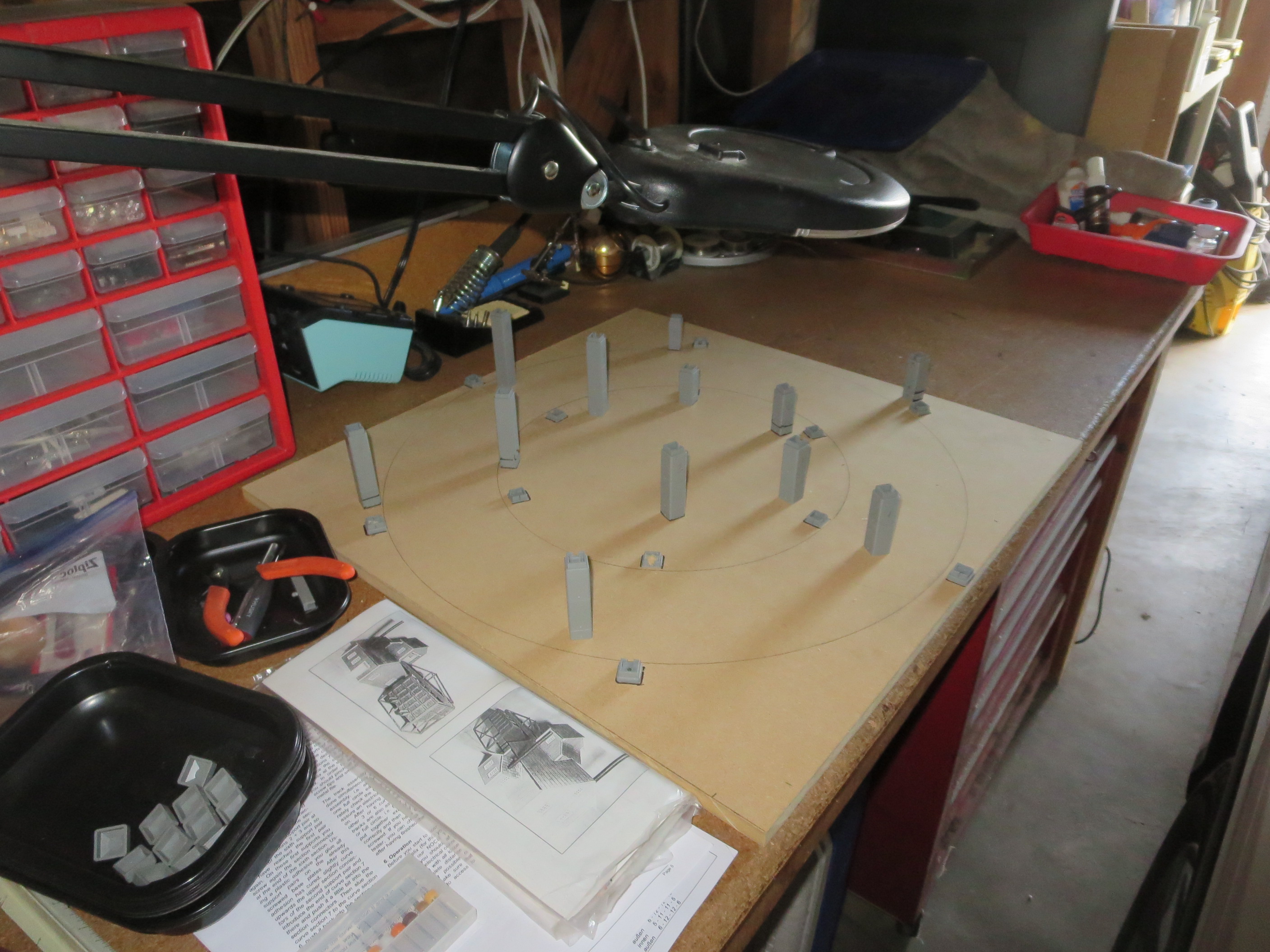

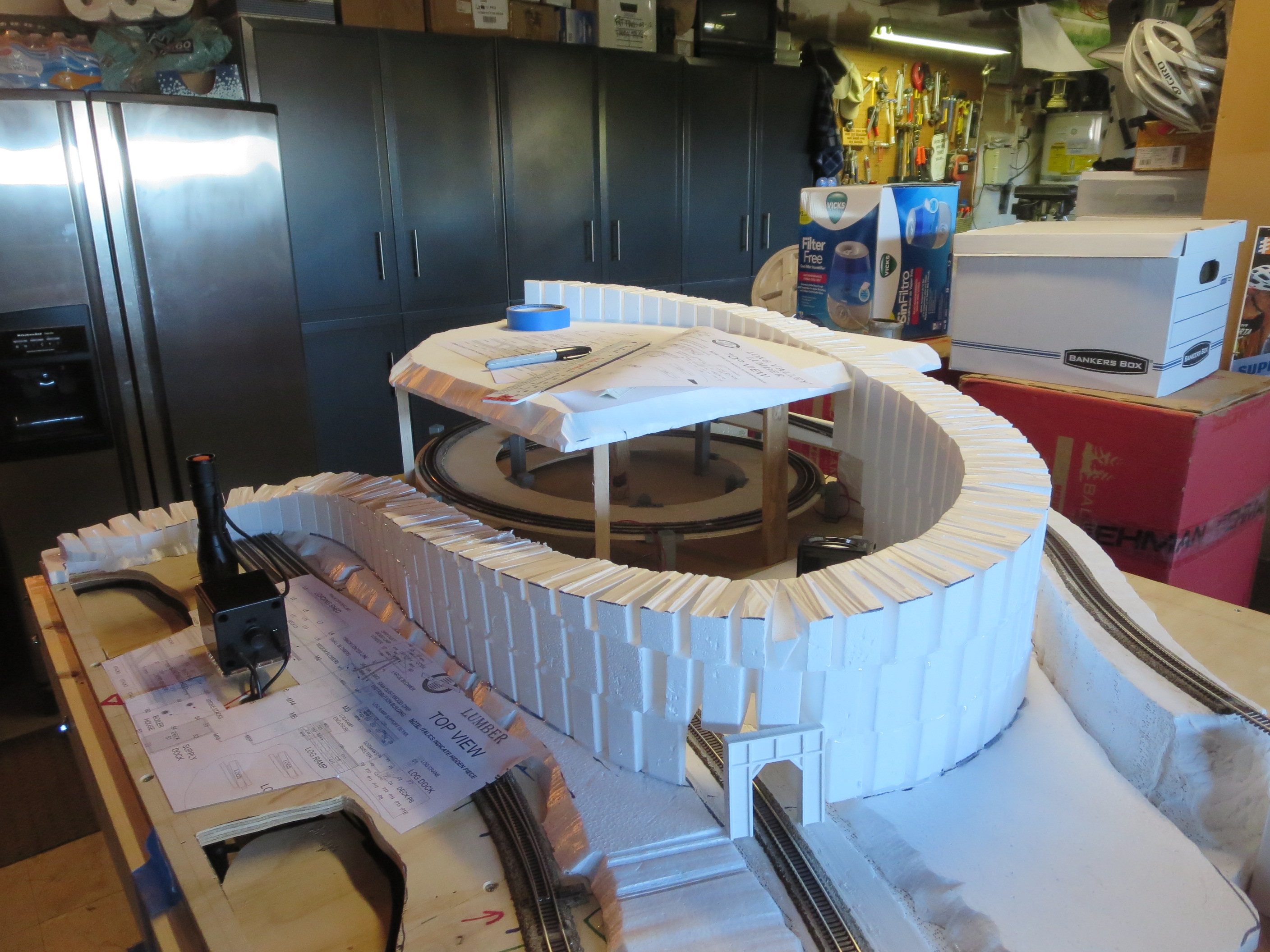
I went through some calculations to determine what size helix I would have to build to get the track at least once around inside the mountain. I wanted to have it appear that the train went off into the distance in one direction, like it was going off to another town, but also come back from the other direction with a significant enough elevation change that it seemed like two completely different routes. I was going to try to shape my own helix ramps, but determined that I could buy one that more-or-less worked for my design. I had to order it from Germany because not too many outfits make them…there are so many gauges and so many different elevation grade change requirements depending upon your design, as well as a limited user base, so I was lucky to find one that I was able to incorporate into my plans – it was sort of a chicken-n-egg thing to re-design my layout to accommodate what I could find. All-in-all, I think I made a good decision not to try to make my own helix.

Finally, after a lot of planning and work over about three months, I had the entire track in place…now on to the wiring and electronics…
Electrical…

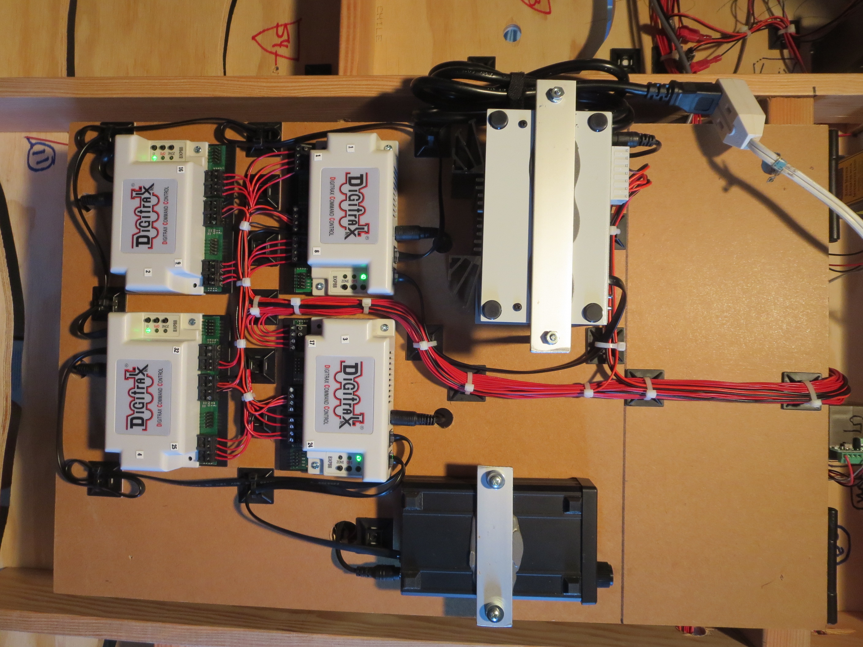
Overview The electrical side of this layout is pretty cool (at least in terms of 2018 technology!). The system uses a technology called DDC (direct digital control). It allows one throttle controller to run many individual train engines at one time. The switches are controlled by a tablet computer, which can throw individual switches by tapping on tablet icons, or, you can run routes, i.e., control multiple switches at one time. The trains also generate individual sounds that follow them as they run around the track.
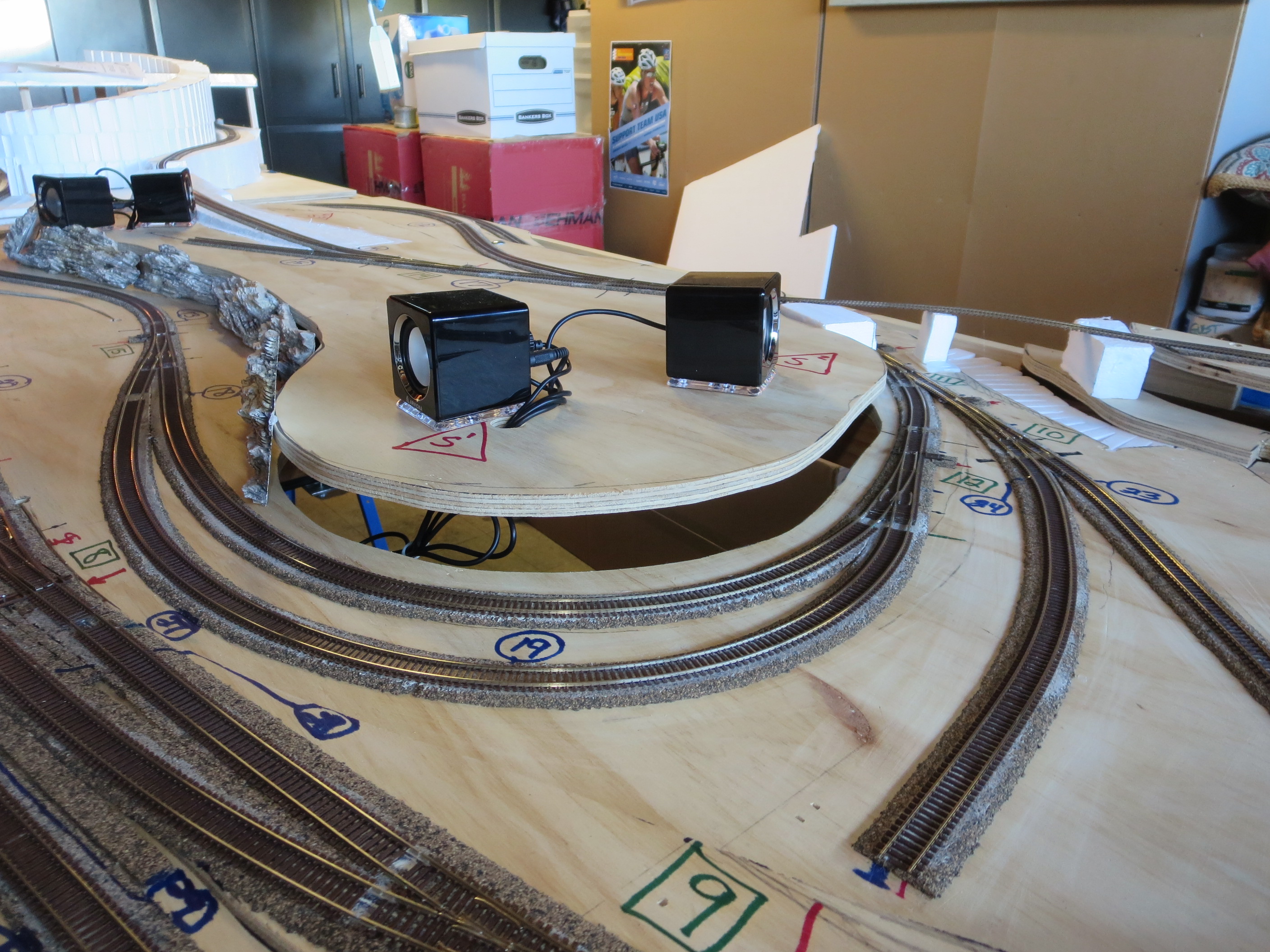
Sound Since N-scale is so small, it is hard to get any of the sound components into the trains themselves like you can in the larger scales. From HO and up, it is fairly easy to install speakers in the engines or their tenders. Those engines also have decoders installed which are controlled by the DDC system. So, when a signal is sent from the DDC throttle by pushing a button, the decoder receives that signal and causes the DSP chip in the decoder to cause train’s speaker to blow its whistle, ring a bell, chuff in sync with the speed of the train, and so forth.

For your layout, there are 5 speakers that are hidden around in the landscaping or structures. The track is isolated into 28 different sections. As the train moves about the layout, sensors attached to these sections sense the current flow change when a train occupies that section. A computer uses those signals to generate sounds that follow the engine around by raising and lowering the volume at each appropriate individual speaker as the engine approaches or leaves the area covered by that speaker – it makes it seem as though the engine itself is producing the sounds.
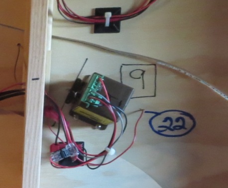
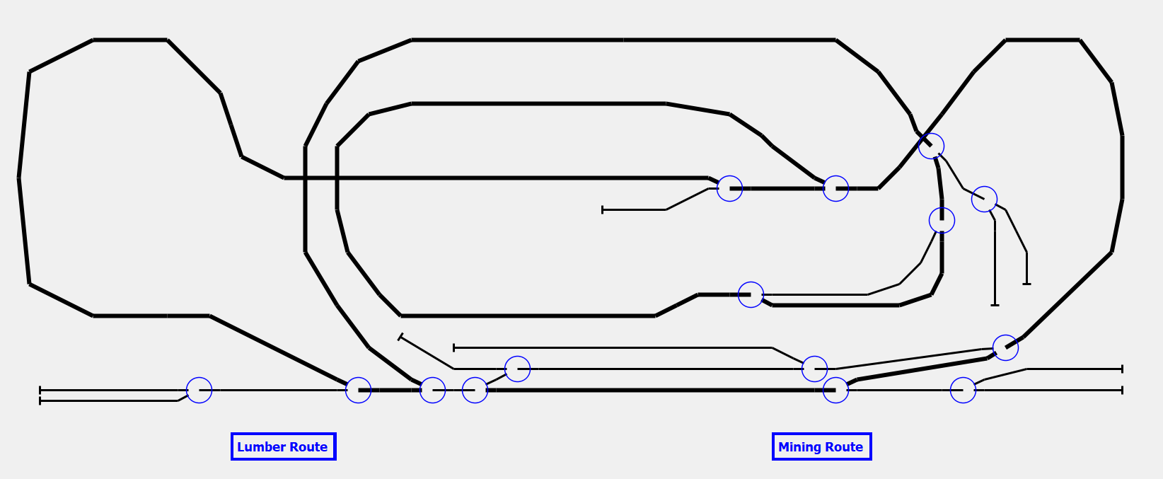
Switches and Routes Each switch (there are 15 total) is controlled remotely by the DDC system. Attached to each switch under the board is a switch motor to move the switch in either direction. The switch motor housing also contains a DDC decoder, which allows the throttle controller to switch the switches, or they can be controlled by a tablet connected into the DDC system via a USB connection. I found some software that I was able to program a graphical representation of the layout and then associate a switch icon with each switch. So, by touching any switch icon, you can move the switch to either its thrown or closed position. Also, you can add icons to the graphic image that you can assign multiple switches to and state what position the respective switches should move to when that macro icon is touched. – in that manner you can create routes that the train will cover when implemented.

Hills and rocks…


Foam Using the foam blocks to make the landscape was new, fun and interesting. I had the basic notion, and then simply began to make things up layer by layer. I used a hot-wire foam cutter and a hot stick to cut the foam sections. Once I was happy with the result, I used a hot glue-stick gun to glue the layers together. The end result is a very light-weight structure that contours to whatever scheme you need to provide the changing elevations.
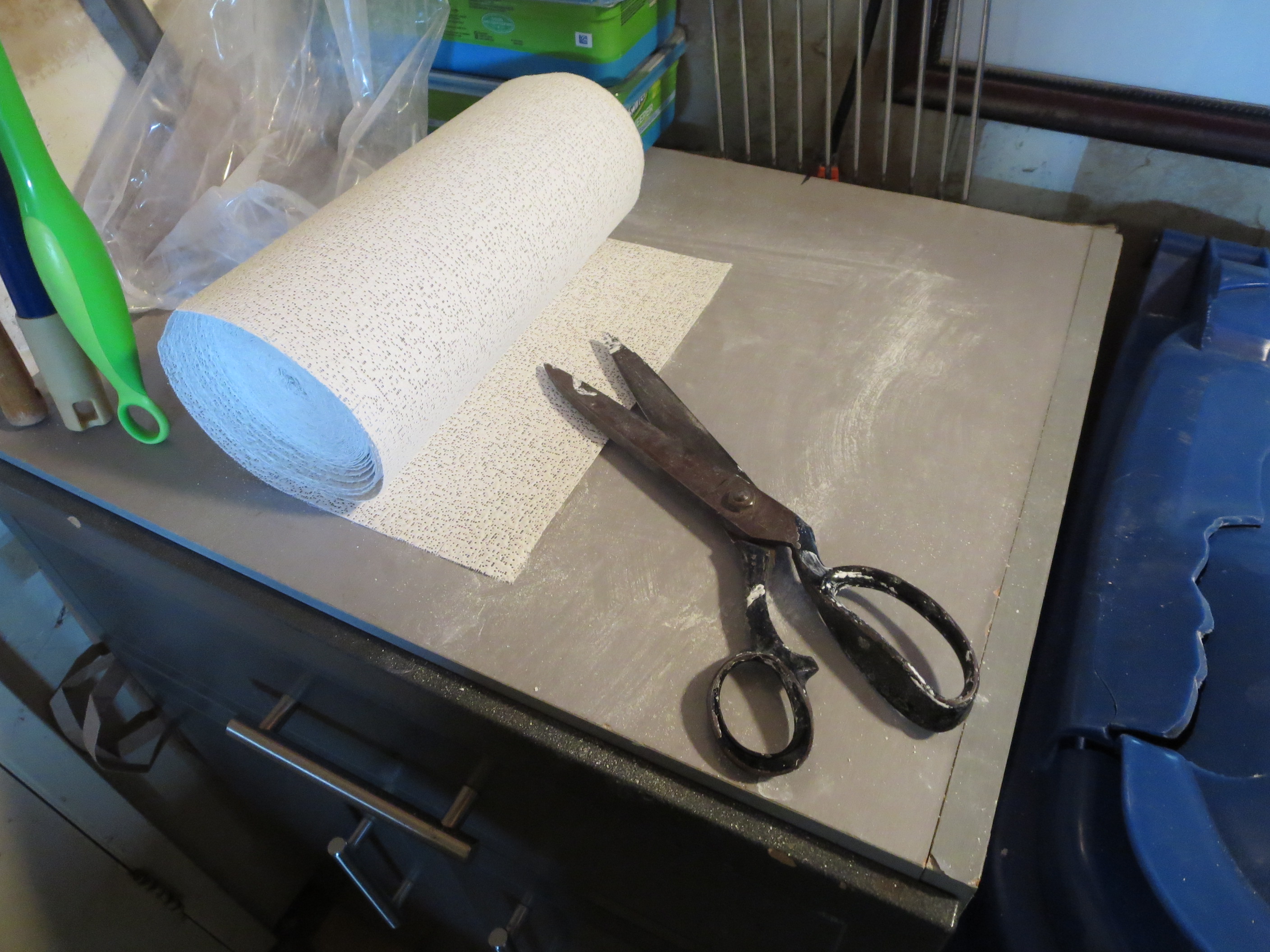
Plaster cloth Once the foam was in place, I took a hot gun like I use on shrink tubing and smoothed off some of the edges so when I covered the foam, the edges would not be so pronounced. Then, I used plaster cloth to cover the foam and produce the actual terrain. The plaster cloth is the same as they use to make casts for when you break your arm, for example (ask your Dad about that!)


I built some of the structures ahead of time in order to be sure that the terrain wound up in the right place and the contours were close. One of the nice things about the foam/plaster method is that it is pretty easy to correct if you screw something up, but I wanted things to be close as I could so I would not have to come back and fix!

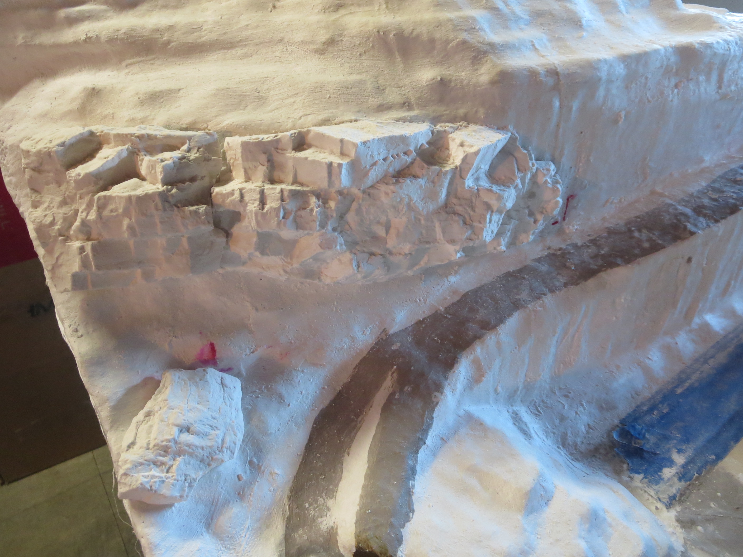
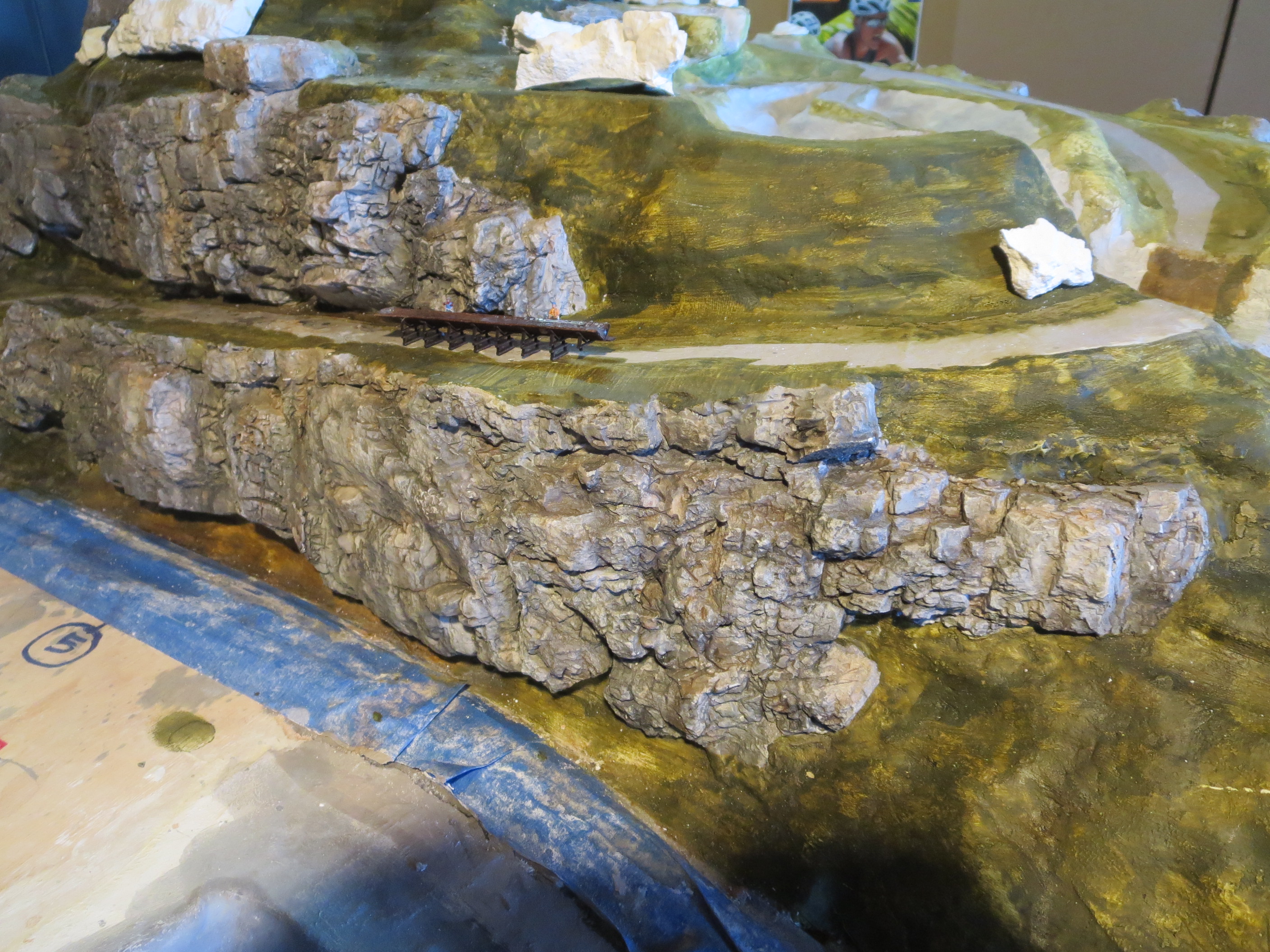
Rocks Once I had the basic underlying structure in place, I began to make rock formations and put them around the layout. Most of the rock formations I make by pouring plaster into molds that I was able to buy.
I made a bunch of rock pieces nominally 4” x 6” and then placed them around to fit my design. Some I made and then glued them to the plaster cloth after they were dry. For others, I poured the plaster into the mold and before it got too hard I pressed it against the plaster face – in this way I could better contour the rock formation for areas that had curves and such. I placed pieces side-by-side in some areas then used wet plaster to fill in the cracks to make it look like all one continuous section.
Making the rocks was fun, and it amazed me as to how real they could look after I applied paint and coloring to them.
Landscaping…

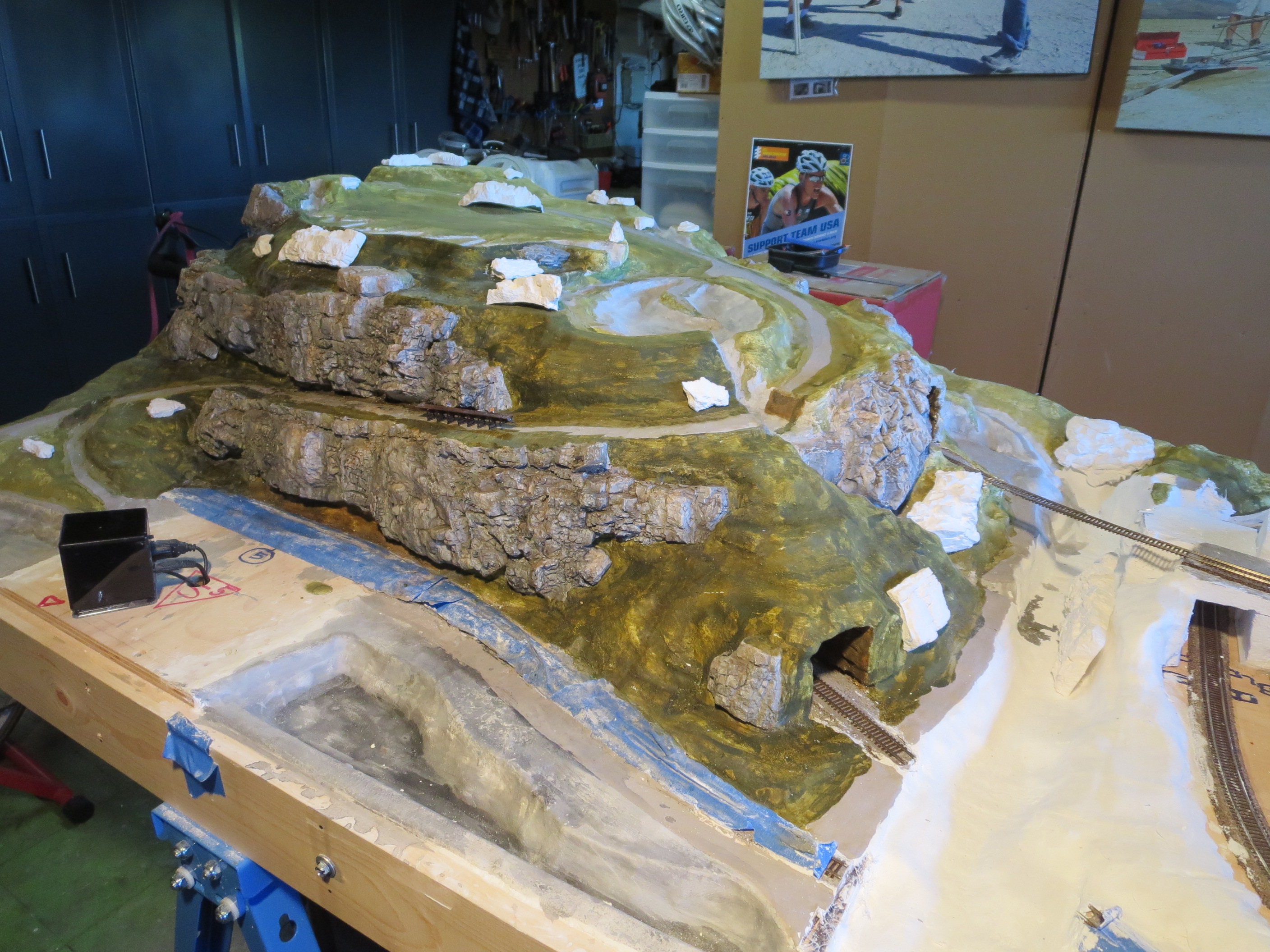
Groundcover Once I had the rock faces done, I began to actually landscape the various areas. Usually I would begin that process by first masking off any areas that I did not want to cover, like the rock faces, ponds, creeks, etc. Next I would paint the white plaster cloth with some green or brown paint – this helps blend in the ground areas with the bushes that cover them. Next I would spray some thin glue on an area, and then sprinkle an undercoat of the colored foam material that makes up most of the groundcover and bushes on the layout. The undercoat is very fine. Even in scale a small piece of “bush” can be pretty big. N-scale is 160:1, so one inch in real life equals about 13 feet in N-scale!
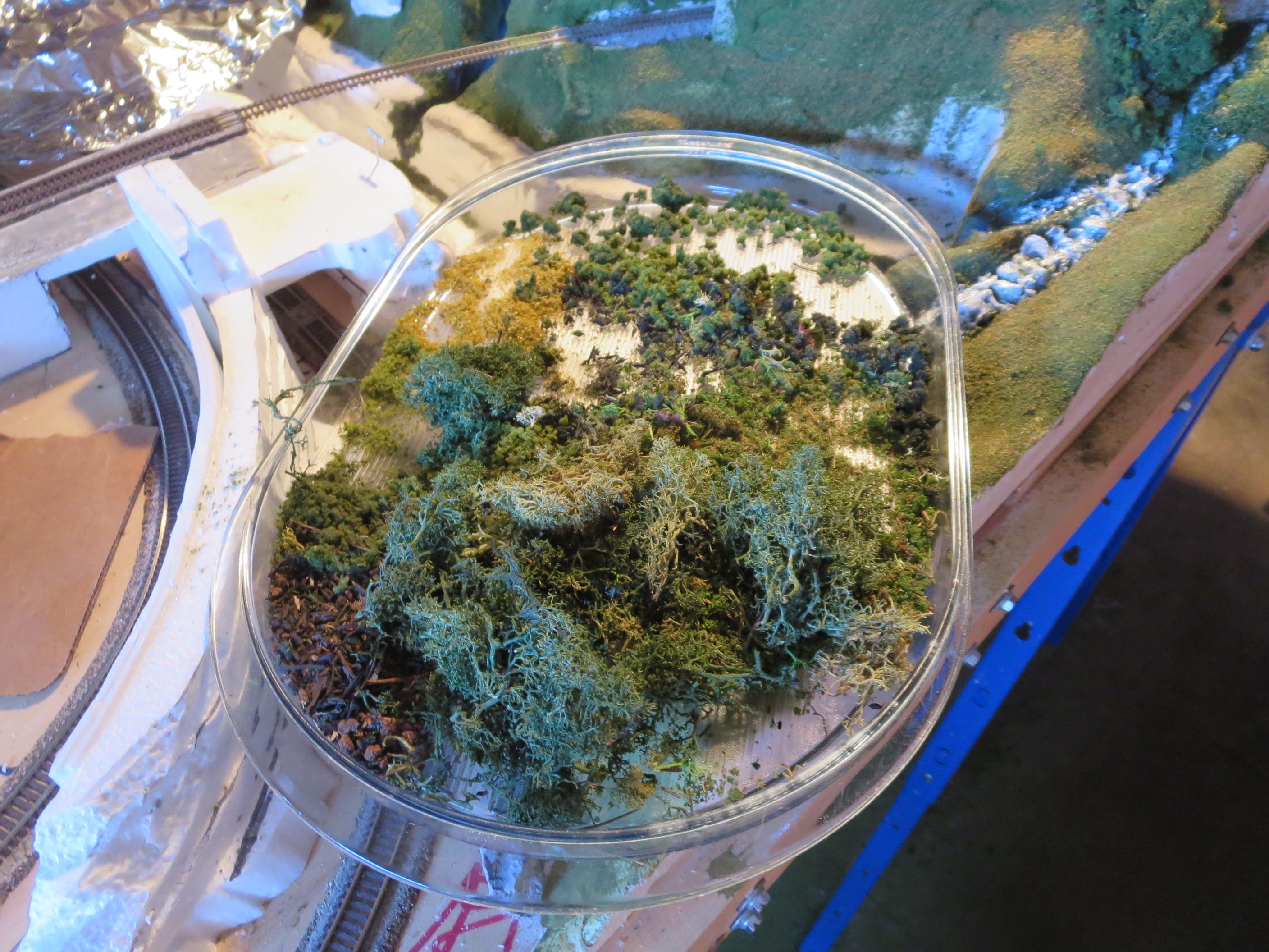
Bushes Once the area was covered with undercoat paint and groundcover, I would then mix up a bunch of different colored “bush” material and add that to the ground-covered areas.

Trees Once the bushes were done, I would then go in and start planting the trees. Trees are one thing that has really improved since the last time I built a railroad. Before, you basically had to make your own trees using lead forms that you could bend to look like tree trunks and branches, then applying some of the smaller foam pieces like you use for groundcover to the form with glue – very time consuming and usually they did not look very good. This time around, I was able to buy pre-made trees that look pretty darn good – I think this is an area that will continue to improve so by the time you start messing with trains, things will be even better!
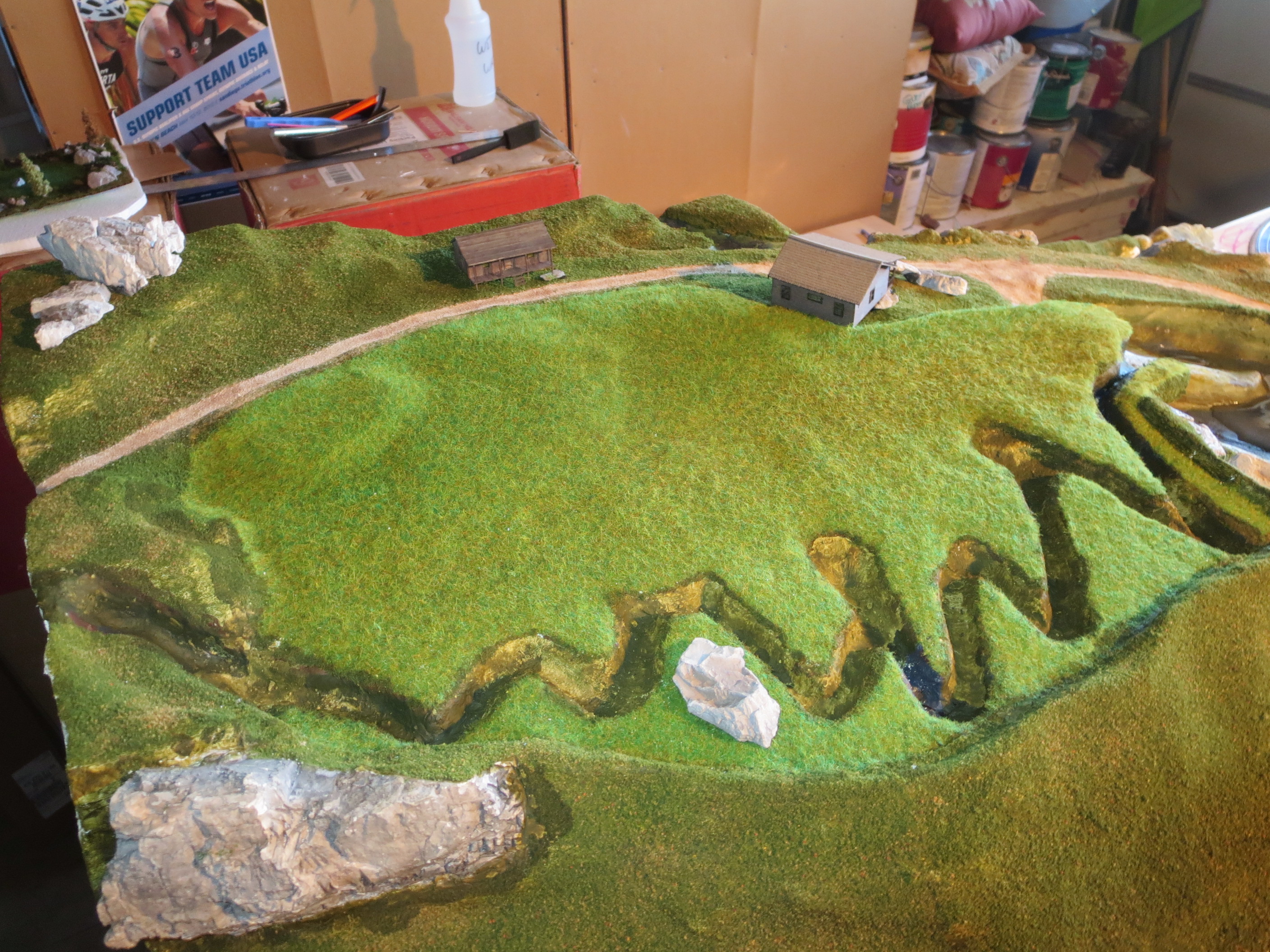
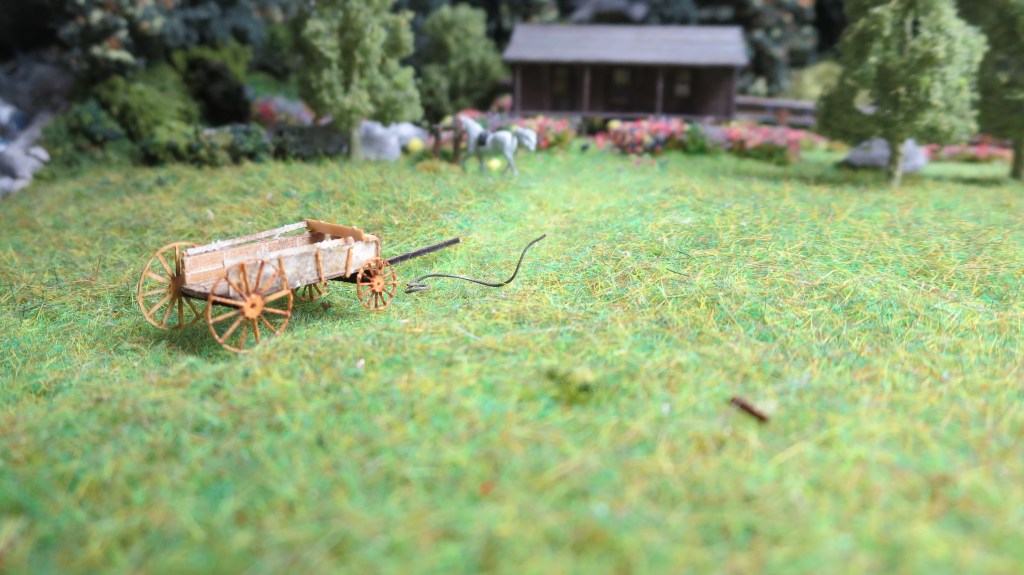
Meadow For the meadow, I used a product that was new to me – static grass. Though you can buy the gizmo to apply the static grass, I built my own from some plans and parts I got off the internet (the internet, or whatever is there now for you is quite common – it did not exist for me until about 20 years ago and was very slow to develop initially – now it is ubiquitous and a huge resource to learn about all the stuff I have done for the layout and a great source for materials).
How the static grass works is that you energize the material with really high voltage so a static charge builds up and so when you sprinkle the material on a wetted surface, it lands and sticks straight up simulating grass – it worked really well for the meadow. The meadow itself is an important part of the layout because Gramma and I always look for meadows when we travel in the mountains – they are a special treat and probably we associate them with one of Gramma’s favorite stories – Bambi!
Water Features…
Flume
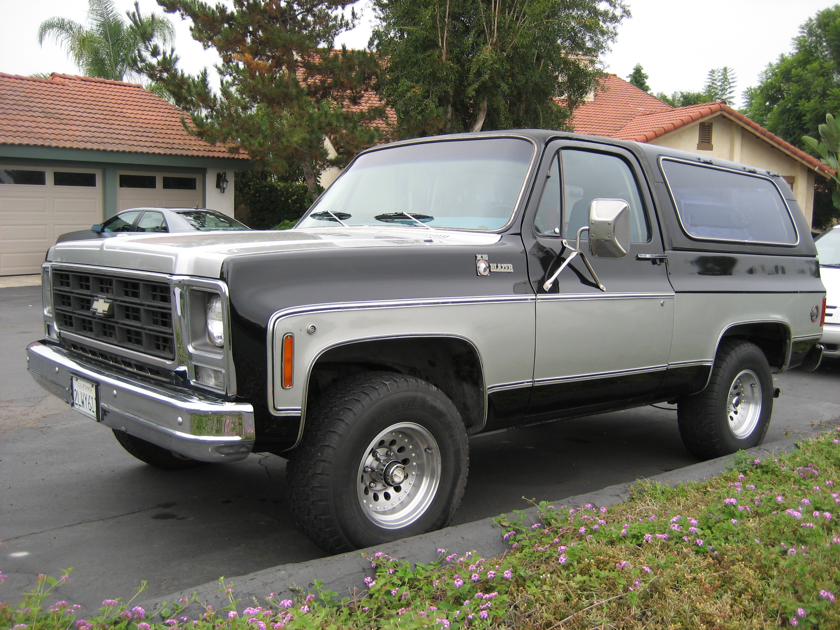
I think one of the more interesting aspects of the layout is the flume. Many years ago when I was contemplating doing a layout, I decided to take a road trip and check out as many mining and lumber areas as I could to get a sense of what I wanted to model. I especially was looking for old ghost towns! So, I climbed into my old ’87 Chevy Blazer fishing truck and headed out.

When I was up in gold and silver mining area near Carson City, Nevada, I noticed some references to a flume that used to run from the mountains above Lake Tahoe down into Carson City. Seems that when the gold and silver strike hit Virginia City (near Carson City), since it is basically desert around there, they did not have enough lumber available to shore up all the mines they were digging. So, some clever entrepreneur decided to harvest the forests around Lake Tahoe – problem was that in those days, it was difficult to bring the tress down the mountain by wagon and it was too steep to run a train down, so they built a flume to transport the trees/lumber. When I was there, they still had some remnants of the flumes. I thought it would be cool to model a flume into the layout.
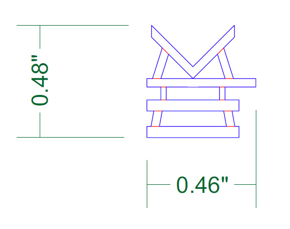
I wanted to use wood for the flume but also wanted to curve it down to the mill. I tried using some angle stock, but could not get it to curve much at all without breaking it. I then tried some plastic angle thinking I could bend it easily by heating it, but struck out there, too. So I just decided to make individual short straight sections and glue them together – it is not really the look I wanted, but it is OK – nothing says they couldn’t have built it that way!!
I did not want to have to construct every one of the wood braces holding the flume up – I think there are over 200 of them! I found a guy that made custom laser cut wood like they use in the structure kits. I designed the part in one of my CAD programs and sent it off to him to fabricate. Even though I had him use plywood (yeah, they make it that thin!), they are so small that they are pretty fragile, and I broke more than a few along the way.
Since I had such tight corners due to the sections rather than curved, I decided that the flume for your layout would transport cord wood rather than trees or lumber. Trees would have looked funny at scale and since they were headed to a mill, having already cut lumber heading down seemed odd (though I did find out that in some cases they would pre-cut rough lumber up above, float it down and then work it at the main mill to produce finished lumber). So I decided that cord wood, the limbs and such left over from cutting, trimming and harvesting the logs, would look OK – they used a ton of cord wood to power steam engines, both the railroad engines as well as the ones used in the factories to power the machines. So, as you can see, the mill does not actually process the wood from the flume other than sorting it and transporting it out on the railroad – your empire does a lot of different things!!
Creeks
The creeks were tough for me to figure out. I wanted to show the water movement and have it look as authentic as I could. As I worked through each particular creek, I learned techniques so that by the time I did the last one I think I did much better. The hardest part was how much of the white paint to use to simulate the turbulent white water and which particular water product to use for any particular area or section. All-in-all, I think it looks pretty good as long as you view from a distance. Of course this is true for any part of the layout – don’t get too close! – but I think especially so for the water parts.
I also had to learn how to plant the rocks around the bottom and to make the water appear to cascade or tumble around them. Some areas are very steep and it is all white water, whereas some areas move slower so that it appears to be just sitting there. Also the amount of dye to use in the mix to get just the right amount of transparency was tricky. Lots to learn along the way – hopefully all that I did learn will help me when I do the river down the middle of the layout, which at this point is still to do.
Meadow

The meadow creek was important for me since I have seen some beautiful meadows made even better when water moves through them. It was pretty easy to do. I just had to be sure to seal the bottom well so the water stuff would not leak through. I finished the surface off with another product after I poured the creek itself which allowed me to stipple it and make it look like it is flowing and has some wind blowing on it.
Mine/waterwheel creek
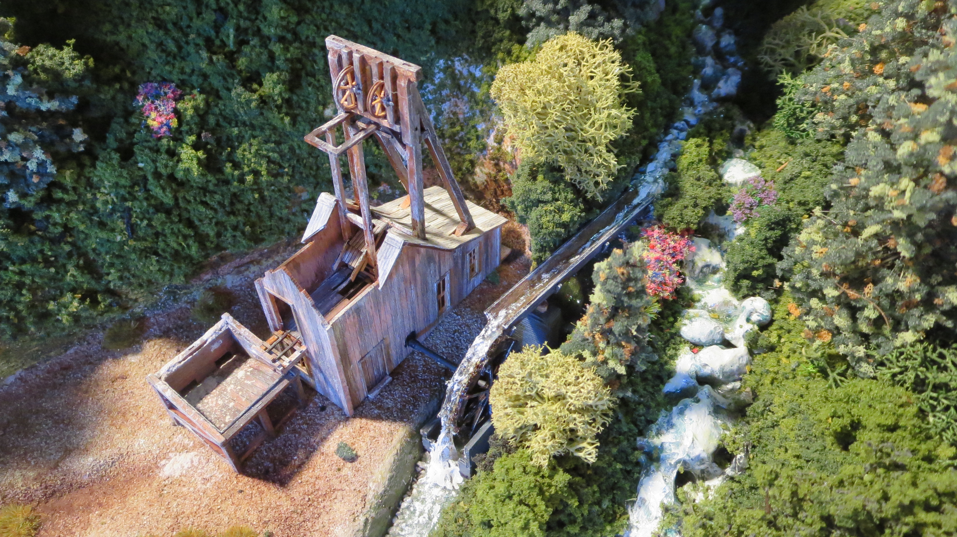
One of my favorite creeks is the one on the backside of the meadow mountain. It flows down to the river and is diverted for the mine waterwheel. It took me a while to find a kit-based wheel – I thought I was going to have to make one from scratch. After quite a bit of searching, I found one in a grist mill kit that I robbed to use for mine. The idea is that the creek water powers the wheel, which is connected by a shaft to the mine, which is then used to drive a pulley, which can raise and lower the ore cart up and down in the shaft.
Double waterfall
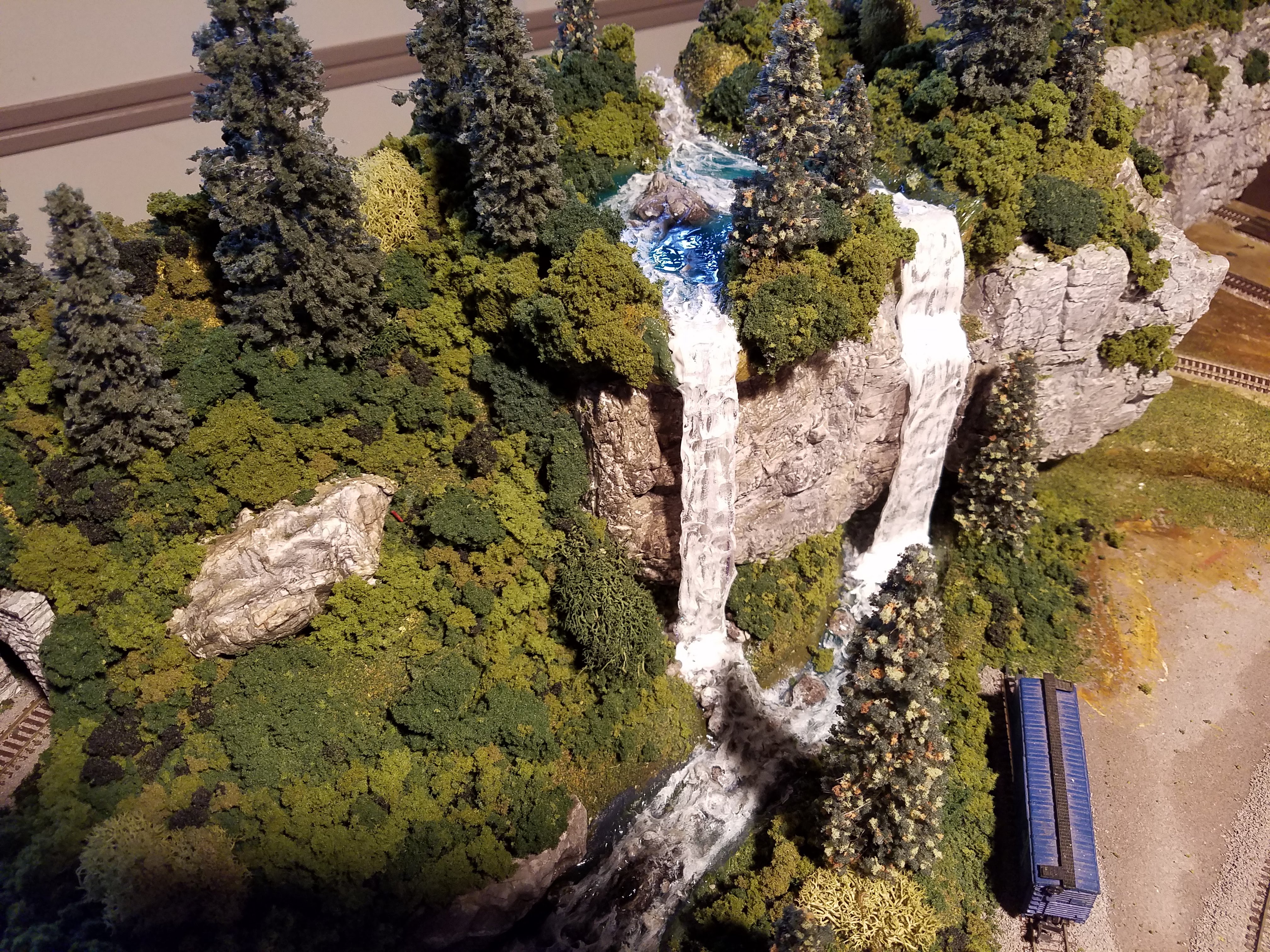
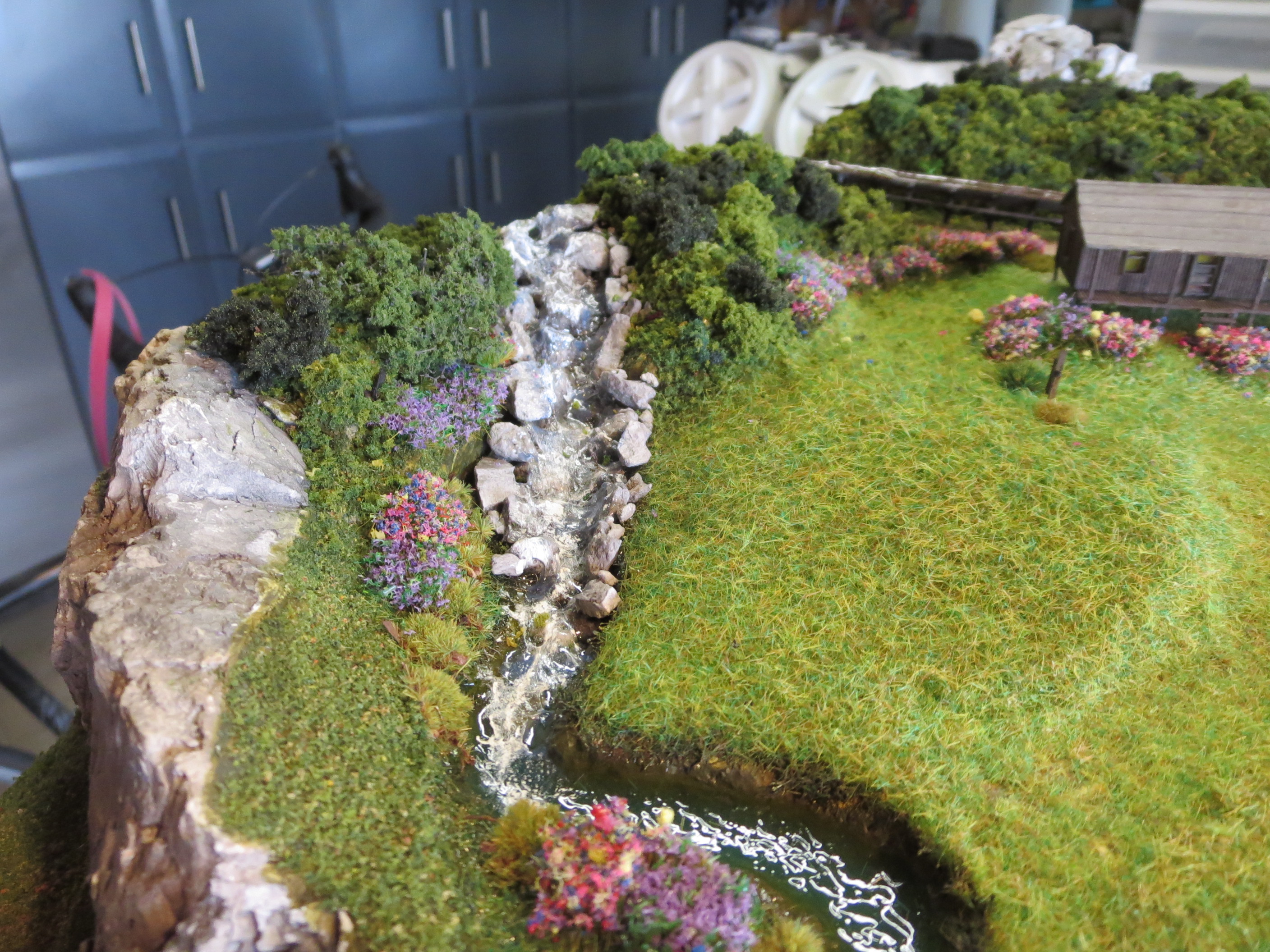
As I mentioned, as I did more and more of the water stuff, I got better. By the time I got to the creek that sits north of the town (the wide part of the benchwork is east-to-west, west being over at the lumber mill side), I felt I was getting pretty good. This creek has a lot going on.
It is fed from a pond up above that has two waterfalls flowing down in to the creek. The water is moving quickly there so it is almost all white water spilling around the rocks and banks. As it moves on down, it widens out so it slows somewhat and has less white water as it continues on down to the outlet. I got lucky and the translucence aspect of the water in the creek is right on. I also like the waterfalls, the better being the northern one.
River
Since I am lobbying for the train to one day come inside from the garage and go up into the office area that Gramma uses, I split the benchwork structurally so that it can be separated into smaller sections facilitating a move. The divide is at the river, which runs south-to-north through the middle-left of the layout. I made it so that the river could be cut/sliced down the middle so the layout separates -hopefully without too much grief it could be rebuilt after the move – at least that’s the theory! The river’s name is the Evergreen.
Pond
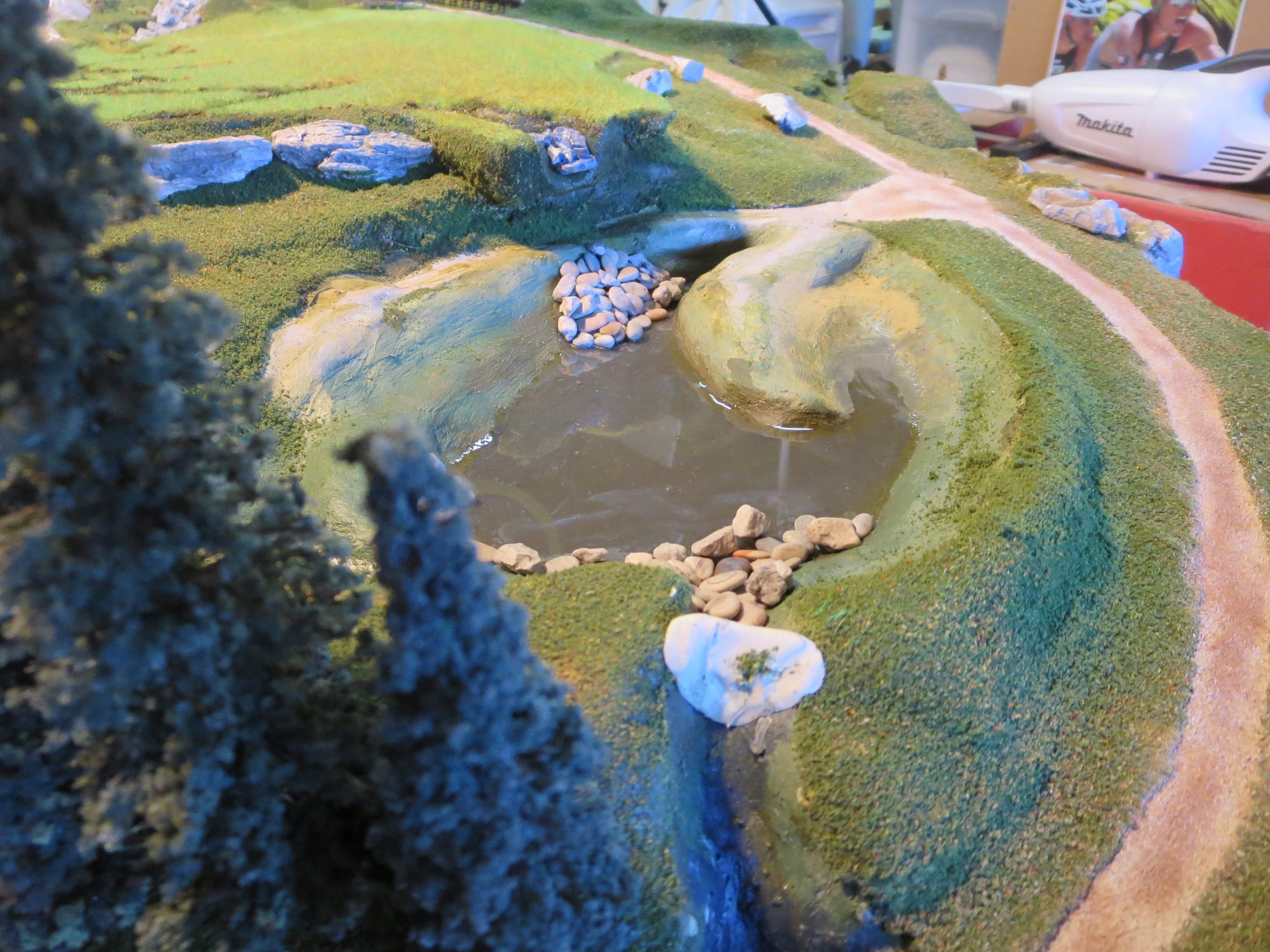
My first water task was to create the pond just below the meadow. I wanted it to show some detail below the surface and to have a couple of fingers of land project out into it. I had also planned to have a dock and boat scene in there, but once I laid things out, I felt that the pond was too small. It is so small that I think someone could fish it from the banks and cover it pretty well, so, when I get to it I will park a canoe or two on the bank and leave it at that – at least that’s what I am guessing now – that’s the nice thing about creating the layout – it keeps evolving and changing as I digest things and work things out over time. Some stuff I need to plan up front and some I can wait until a good idea comes along.

Anyway, not too long ago there were not a lot of options on what to use for the water itself. For a pond, you had to mix epoxy or use some other product that would yellow over time. Then Woodland Scenics (WS) came out with a one part product (i.e., no mixing) that will not yellow over time but you could only pour an 1/8” at a time. So doing something deep like the pond took a long time. Then they came out with their deep pour product that allows you to pour up to ½” at a time – perfect for the pond. It is a two-part product that requires strict attention to how much of each part you use, but it works well and supposedly will not yellow (by the time you read this you should be able to confirm that claim!). I think it took two pours You have to really seal the bottom and dam up any exits (like the creek heading down to the river because the stuff will seep and creep everywhere since it is so thin. It is also colored with some dye that you mix in. It also determines how much you can see through the surface to the bottom.
I was able to create a little waterfall rom the meadow creek above that you can walk under! The pond is Gramma’s favorite part of the layout so far.
Structures…
Era

A lot of the structure, building and engineering around the site was first done in the mid-1850’s.The timeframe for the current layout period is the late 1800’s/ early 1900’s. There were cars and electricity for buildings by then, but only in the bigger cities – but even though they had the railroad, a small outlying town like Walton Valley was still relying on horse drawn wagons and carts, and steam for industrial machines – even waterwheels for power were still around! AT some point I will do a write-up of the history of the area and how it became known as Walton Valley and how all the industry developed over time.
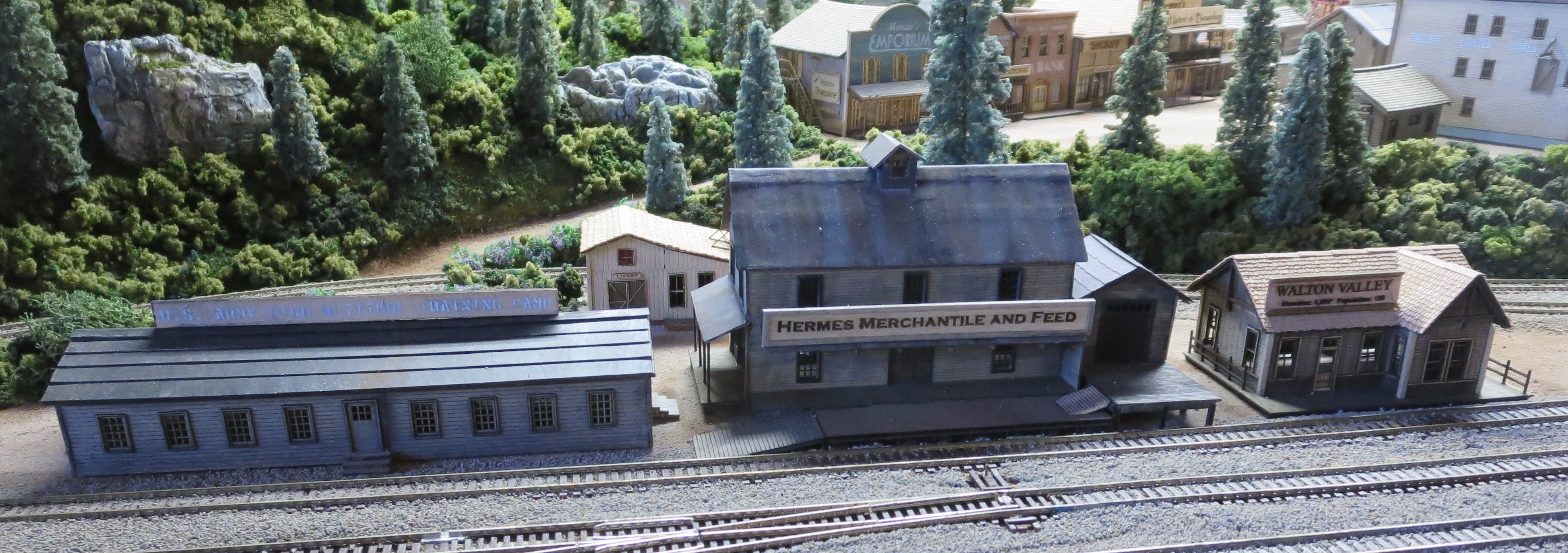
The elevation of the town of Walton Valley is over 4,000’ (check out the sign on the railroad station). It is late spring and all the snow has melted, except for a few spots under the trees up on Meadow Hill.
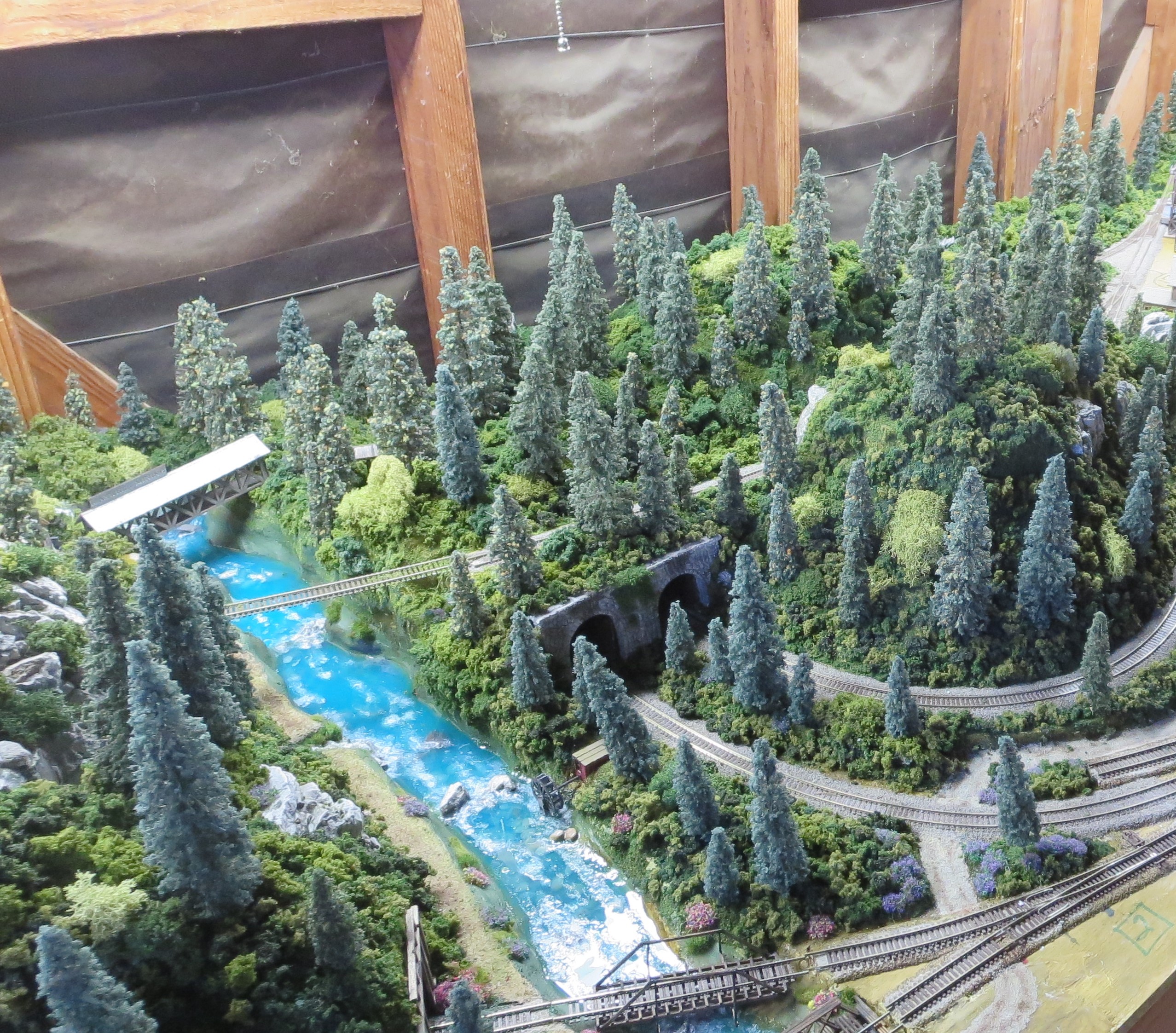
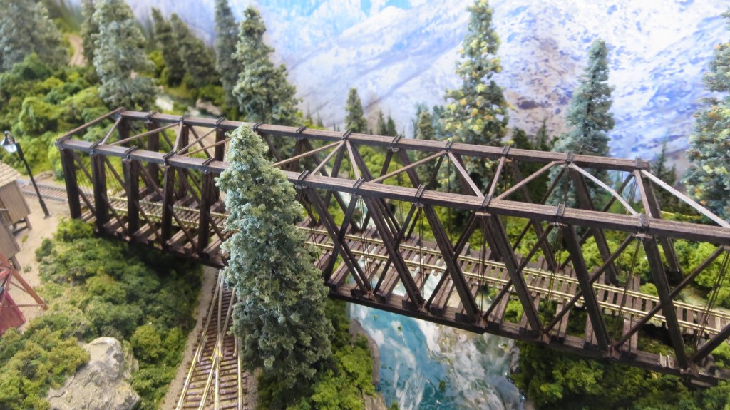
Bridges and tunnel portals

Most of the support structures around then were still wood, with a lot of stone work thrown in later on – usually when something wooden deteriorated and needed re-building. Even though concrete had been invented most of the structures had already been built or re-built so not much concrete had been used – you can see it in some of the building foundations for some of the later-built structures.

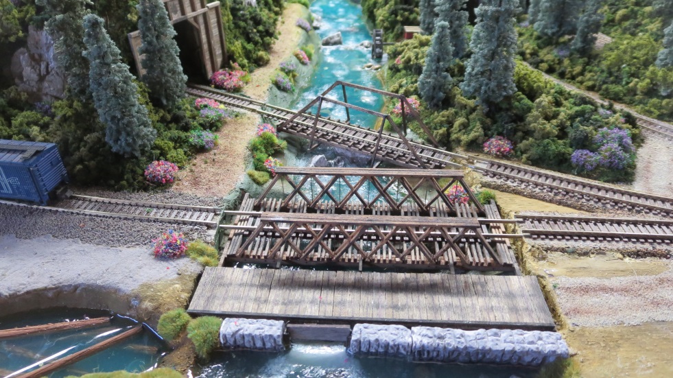
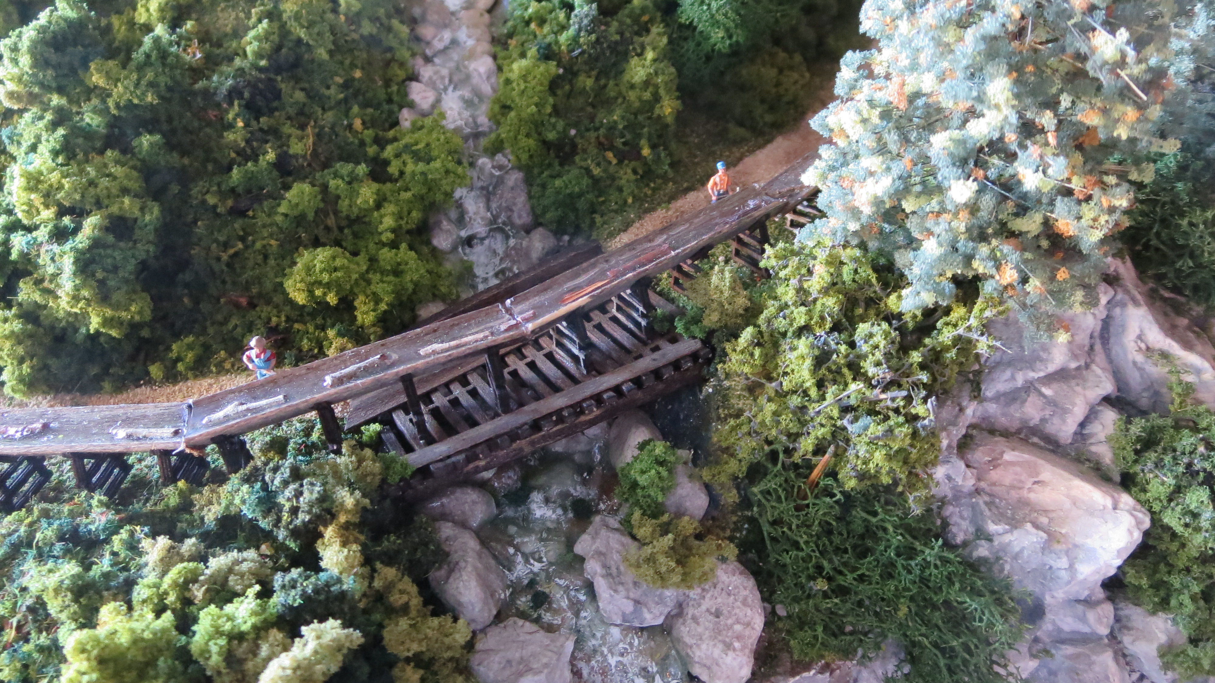
The bridges are all old and made of wood – some of the spans, like over the river and over the double-waterfall creek were extraordinary for their day and had required state-of-the-art engineering at the time. Most of the tunnel portals are still wood, though a few were re-built several years back using stone from around the area. In the case of the portals in the hills to the east, they were simply carved out of the mountain since it was all rock there and so strong.
Some of the bridges used laser cut pieces, but the two long ones are almost totally stick built stick-by-stick from scratch using plans/templates included in kits of strip wood – tedious when the section is scaling 2”x 4”’s!!
Mine (Maxwell Mining)
They now take silver ore out of the mine (originally it was gold, but the big vein played out years ago) – it’s not a big amount, but it is still profitable after around 100 years of activity there. The shaft goes down over 500’ and is a two-man operation – MWB Enterprises owns the mine and the mineral rights. It was the source of the wealth that originally allowed the development of Walton Valley and the building of the Walton Valley & Truckee railroad (W.V&T. RR).

The ore is not processed there. They remove the ore and transport it in carts across the river via the covered bridge (gets very cold and snowy in the winter here), and then dumped into train ore cars from the ramp near the tracks.
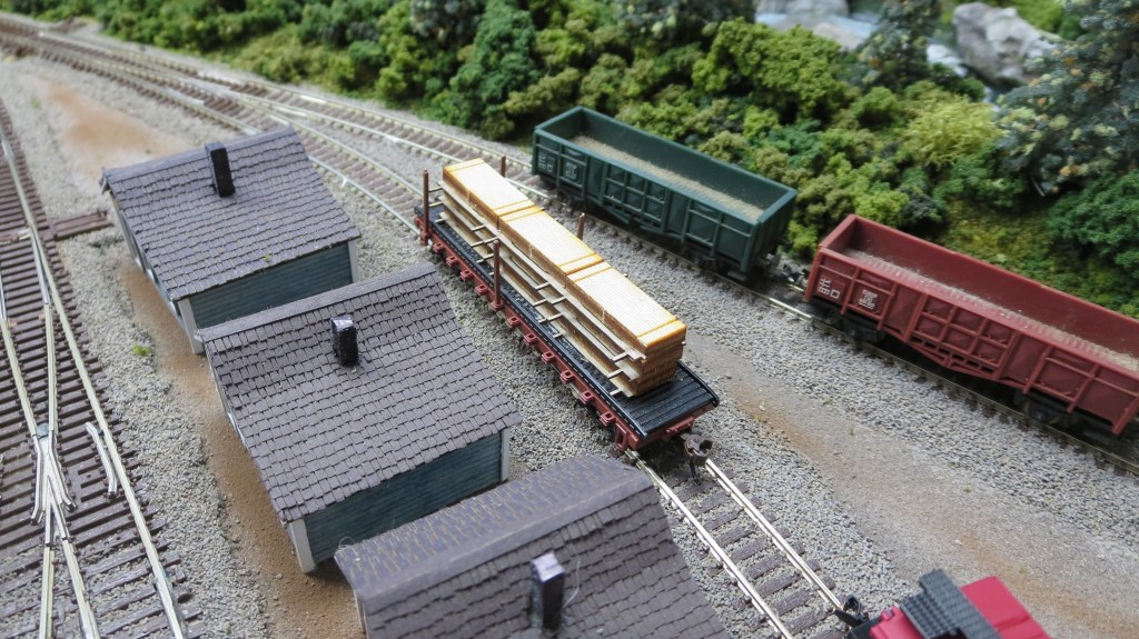
Lumber Mill (J.W. Lumber Company)
The lumber mill is the main industry of Walton Valley and employs most of its citizens (pop. 186 at last count!), some who live around town and in the dorm building near the railroad station, and some travel to a nearby settlement where the rent is a lot cheaper. The mill produces both rough and dimensioned lumber, and at times has produced railroad ties, though not much of that anymore since the railroads are generally already built-out in the nearby areas.

Logs are harvested in the mountains and either brought to the mill by rail or are floated down the big Chute River to the south and funneled into the log pond near the mill.
The Evergreen was dammed to create the log pond. The dam is still used to control the flow of the Evergreen and the level they maintain in the log pond.
Much of the lumber is used by the factories in town, but most is shipped by rail to nearby towns.
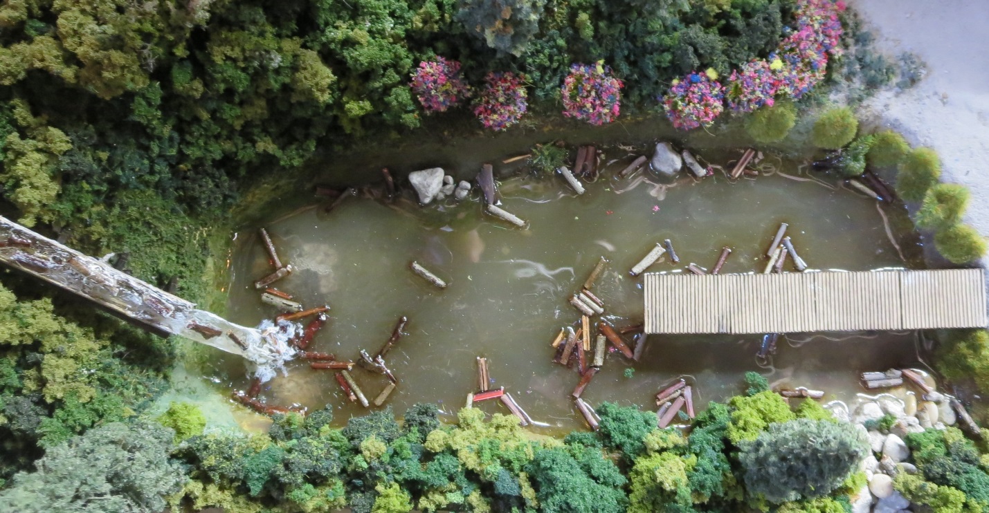
Though the cordwood (J.W. Cordwood Flume Co.) is not processed in the mill, the mill facilities are used by the cordwood company employees, and the area is used for sorting and staging operations once the cordwood is floated down the flume and dropped into the pond.
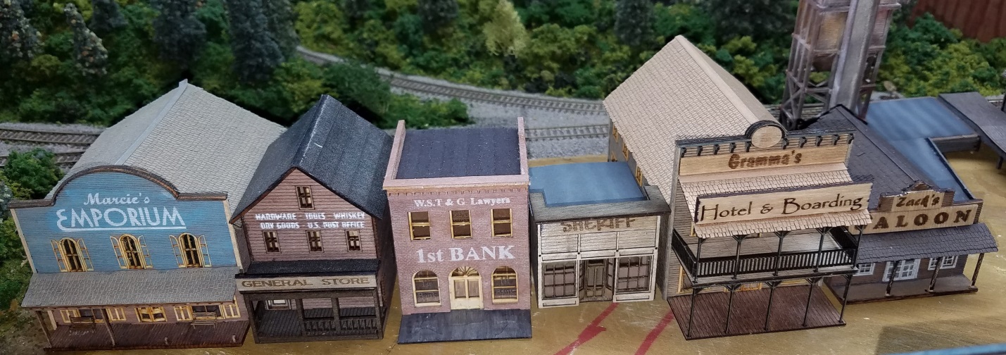
Town
Walton Valley town, east of the lumber mill, has lots of shops and taverns, a hotel, and a bank, and, a sheriff to keep law and order in what is usually a quiet community – though the mill and mine workers have been known to have a pretty good time come Saturday night, so he’s needed… (at this point, the town is laid out but still needs scaping and details)
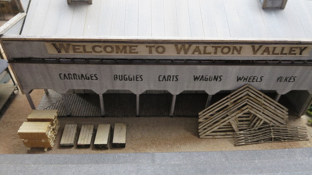
Factories
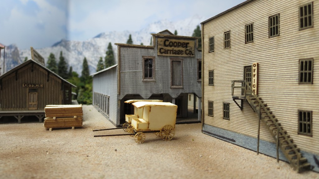
There are two large factories in town – one, the Gabriel Wood Products Co., produces mainly pallets and the other, the Cooper Carriage Co., produces carriages, wagons, carts and wheels – though wagons and carts are on the wane, the factory is still a profitable industry .

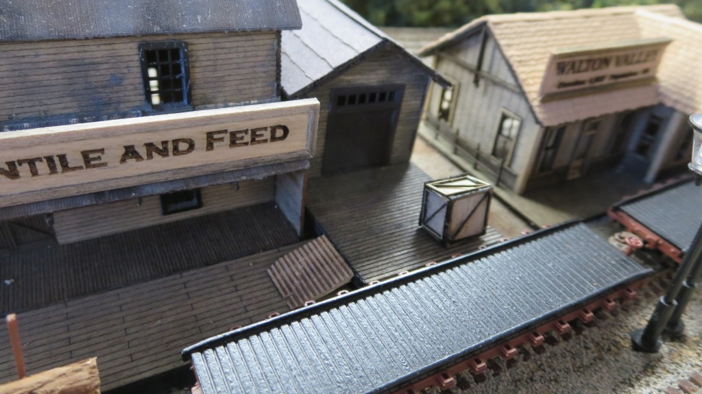
Signage

I wanted the signs around town to be personalized and not simply the ones that came with the various kits – sometimes they were inappropriate to this town and many were not of the proper vintage or era.
Usually, the kit signs were either decals or dry transfers, both of which are hard to make look natural and conforming to the mostly wood siding of the town buildings. I have made stencils before when I built my model rockets, so I knew I could personalize them, but came up with a different idea.
In the 1st Bank kit (see above), I found a sign stencil that I used and liked that I actually painted the signs right on the bank. I asked the manufacturer of the kit how he made the stencils and he said that he used the same laser cutter that he used to cut the wood for the kits.
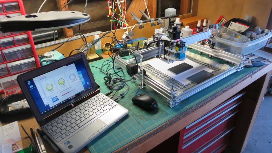
So, I started looking at laser engravers/cutters but at first thought no way since they were so expensive (up to $50,000 or so). I kept looking around the internet and saw that there were some hobby laser engravers that were under $1,000 – then I saw a laser engraver kit for less than $200 – no way that could work, right?
Well, I looked at a lot of the reviews and decided to give it a try. I really questioned whether such an inexpensive machine could actually cut out stencils for letters that were often to be less than an 1/8” tall to even come close to looking scale (160:1) – remember, most of the buildings are only about 1 ½” high! So, I ordered one and waited patiently for it to arrive on the slow boat from China (literally).
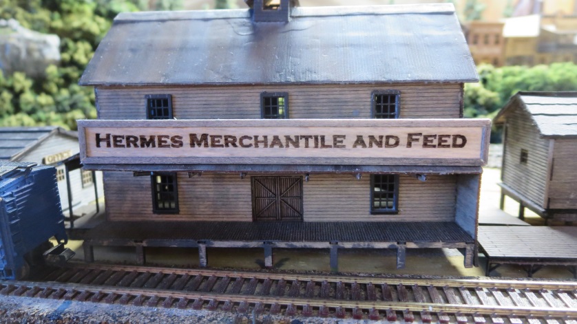
I put it together and was pleasantly surprised to find that it did great – very accurate. Though the stencil approach turned out to be very tedious, I found that I could engrave wood and make signs that way, so, most of the signage is burned wood, but I was able to get some color into play with the stencils that I could make workable.
What’s left…
So, here in November of 2019, I am at the end of the major construction. The town layout is done and has some dirt in there for the streets and such. I decided not to elevate the town site to accommodate the two speakers that went inside the two factories – rather, I cut some holes in the plywood and recessed them, so all five speakers are well concealed now…
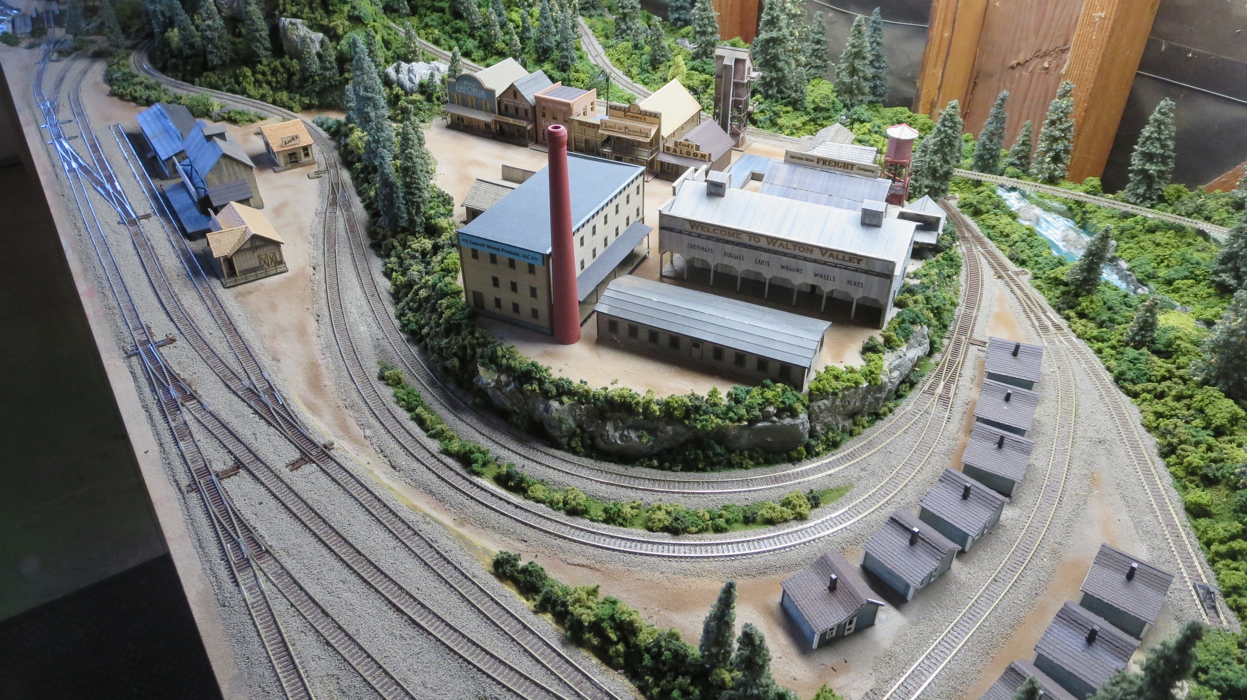

The remaining task is to fill in scene details around the layout to make it look more “lived in” – I’ve added a bit, but maybe I’ll leave the rest for you and I, Max, to do together…here are some shots of my progress…

As you can see, this is a town mostly focused on lumber products…


Revised 11-18-2019

Frank, this is absolutely incredible! I truly had no idea what it all entailed AND I think it’s the coolest thing ever that you made the story, the narrative and the text letting not only Max but other (possible) future grandchildren to know the “story behind the build”. What an EPIC adventure. As always, you never cease to amaze me Mr Hermes
Kelly – thanks for the nice words!