Well, we finally have all the elements worked out in order to be able to assemble our voice-directed robot!
Parts List.
- Robotis Bioloid Premium (RBP) Type-A Robot
- Raspberry Pi 3 A+
- 16GB microSD card
- Respeaker 2-Mics Pi Hat
- Grove Temperature & Humidity Module (optional)
- Speaker with JST 2-pin Connector
- Adafruit DotStar 8×8 Matrix
- 7.6 Volt Lithium-ion Battery with JST connector
- Voltage Regulator
- Short micro USB Extension Cable
- Right-angle Type A USB to Right-angle microUSB cable
- micro USB Cable (any old one – we’ll cut and use the male end)
- In-line microUSB ON/OFF Switch
- Female JST Connector
- Velcro tape, ty-wraps, screws, etc.
Once you have collected all the various parts…
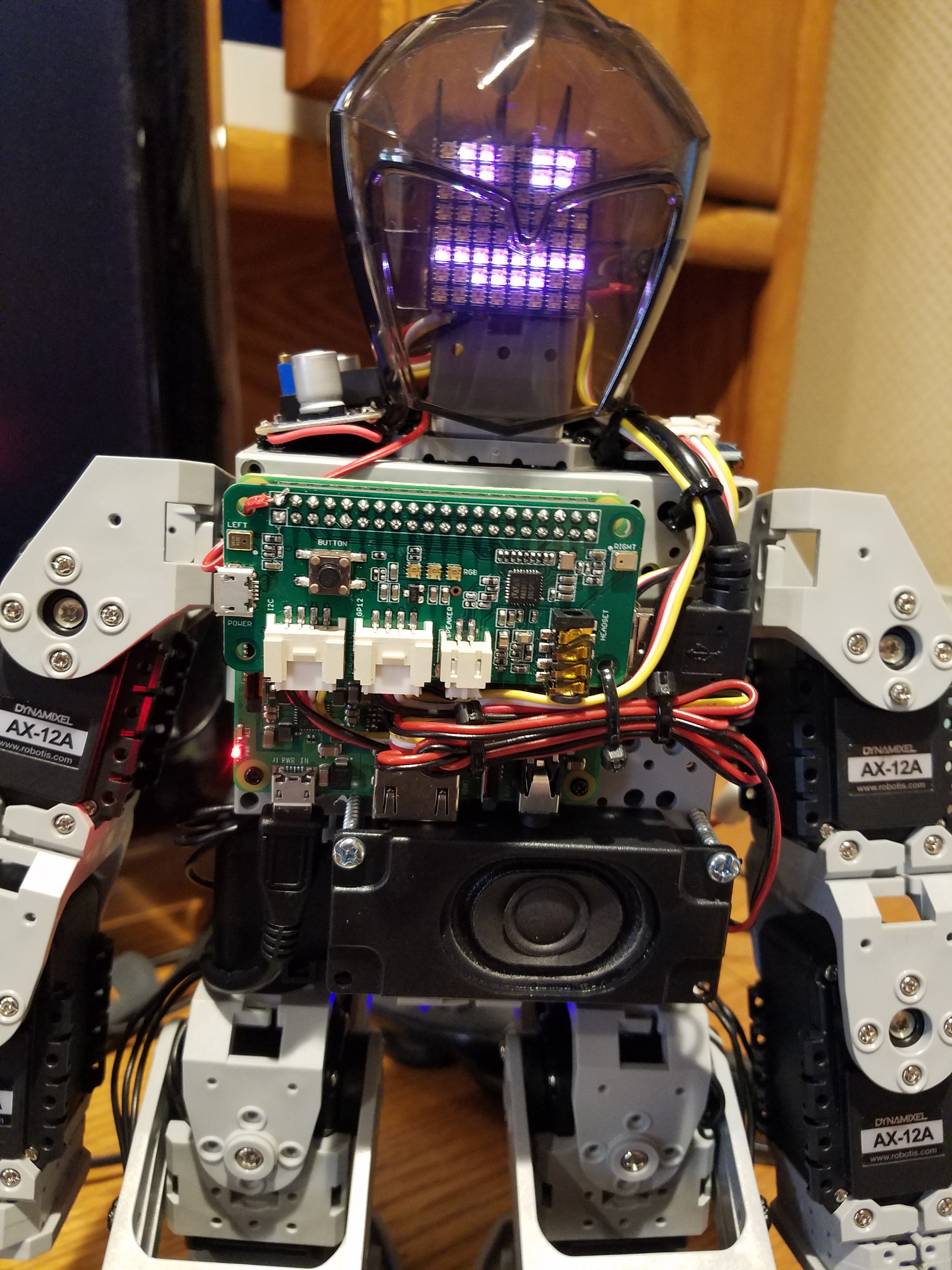
- The main item is to get the RPi mounted to the robots chest
- remove the front semi-transparent chest piece by undoing the mounting screws and unplugging the DMS sensor (note: it is not necessary to have the sensor plugged into the robot, it will operate OK in the command mode we are using it in, it just will not work in the autonomous mode)
- By using an RPi 3 A+, and mounting it as shown, the USB and power cables, and the speaker, can be positioned to stay out of the way of the robot’s actions
- place the RPi to the upper left and mark the 4 mounting holes
- you can find suitable self-tapping screws left over from the robot build
- I used some short standoffs to keep the board clear of the chest and allow for some air circulation, but not sure it’s necessary
- carefully drill out the mounting holes to a size that works with your screws
- remove the front semi-transparent chest piece by undoing the mounting screws and unplugging the DMS sensor (note: it is not necessary to have the sensor plugged into the robot, it will operate OK in the command mode we are using it in, it just will not work in the autonomous mode)
- secure the Pi Hat to the RPi – I just plugged it in to the header strip
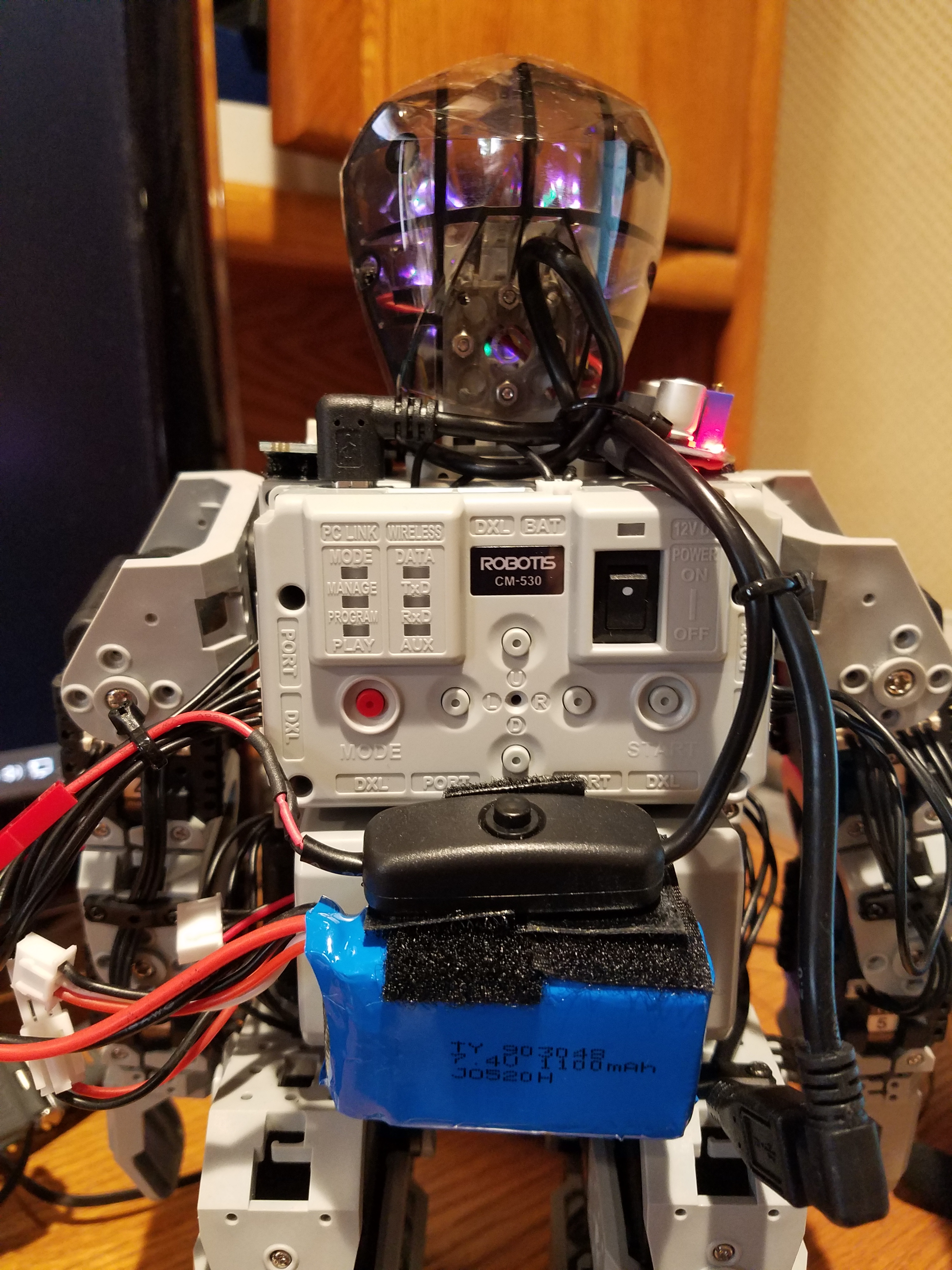
- take the right-angle A USB to right-angle microUSB cable and interconnect the RPi USB port and the data port on the CM-530
- using 1″ sheet metal or self-tapping screws, drill and mount the speaker to the chest below the RPI – connect the speaker to the Pi Hat
- using a short piece of Velro tape, mount the Temperature & Humidity sensor to the robot’s left shoulder and plug into the Pi Hat
- connect the short microUSB extension cable to the RPi and route it to the rear of the robot and secure – I used the extension cable so it is easy to power the RPi from a power supply rather than the battery during setup and programming
- I used a left over ell-bracket from the robot kit to use as a mounting plate for the LED-matrix – I believe it was an F6 piece…I screwed it to the front end of the ell-bracket that mounts the IR sensor in the robot’s head and attached the matrix with Velcro tape…note, I disconnected and removed the IR sensor from the robot, but it is not necessary, there is plenty of room to mount the matrix – in any event, unplug the sensor from the CM-530…
- I used a left-over microUSB cable for the output side of the voltage regulator
- – the male-connector-side of the cable connects to the short extension cable plugged in to the RPi
- – cut the other end to about 4″ length, strip the outer insulation off
- use the red (5V+) and black (GND) conductors (standard color code of USB cables, but test to be sure!) to solder to the voltage regulator’s output pads
- for the input of the regulator, I cut one of the cables to about 5″, stripped it back and connected the red and black leads to the input pads of the regulator; I cut the other switch cable to about 1.5″, stripped it back and solder it leads to a female JST connector which is used to connect to the battery…
- I mounted the battery and switch to the robot’s battery using Velcro tape
- try as best you can to dress all the cabling to keep it out of the way of the robot’s actions!
