Below you will find pictures highlighting my deep dive into model rocketry…they will be somewhat in chronological order to show techniques and products I learned about along the way, and some of the results!
I started back into model rockets in 2009…I had not even thought about them since I was a kid back in the early 60’s, when I would trek out with my brother and fire off Estes rockets and motors…I was in a hobby store one day and noticed some Estes stuff on the wall and it brought me back to those days…I did a little looking around and found out that they have a model rocket club in San Diego – they fly out in the Imperial area east of the city…I headed out there at their next launch and was amazed at how sophisticated some of the guys’ rockets were – especially one built by a guy named Mark Clauson – he got me hooked!
Seeing Mark’s rocket soar away (he was going for some sort of an altitude or speed record and used what is called a “moonburner” (low thrust, long burn time)) and going though the local parts vendor’s (Jack Garibaldi) on-site trailer seeing so many goodies pushed me to get on the internet and find out more about high-powered model rocketry (motors that are 100’s of times more powerful than the little Estes motors).
I found lots of information about such rockets and their fabrication…lots of rocket kits and loads of different motors available…also, I determined that the club was an affiliate of the National Association of Rocketry (NAR)…NAR has an ascending set of levels that you can be certified at, which then allows you to purchase the bigger and bigger motors as you progress through the level structure…so, off to achieve Level 1!
At the time, I did not think I was intending to go high – I had seen several rockets at the launch zoom off and basically go out of sight – but rather build rockets that seemed more realistic with slower ascents and lower altitudes (this poroved to be a false assumption as I progressed in the hobby)…
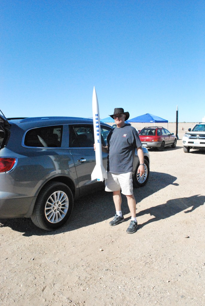
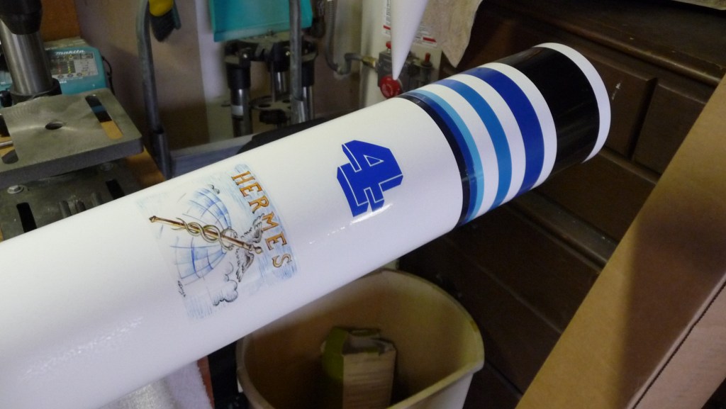
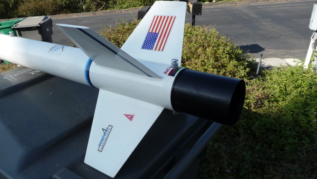
This is Hermes 1 – I numbered my rockets and their various configurations in numerical sequence rather than give them pet names…this is my first rocket, a mofified Aerotech G-Force, and the one I used to qualify for my NAR Level 1 certificate…the following is a detailed description of its fabrication and flights…
Hermes 1 – a modified Aerotech Aerospace G-Force The major modification was to change the motor mount (MMT) to a 38mm diameter from stock 29mm and using a GROOVE-LOK from Giant Leap Rocketry to anchor fins to the MMT. Additionally, I used 0.187 plywood bulkheads and centering rings throughout. I added an electronics/payload bay to the sustainer section and changed out the chute for a larger one. For ease of use, I also added an Aero Pac Quick-Change motor retainer.
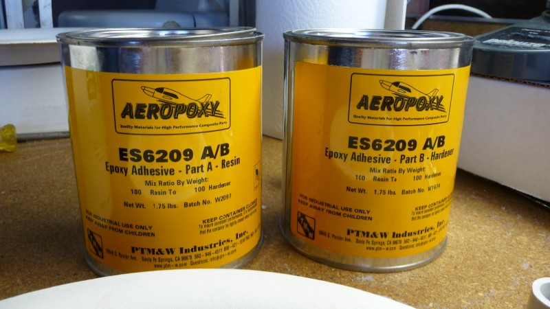
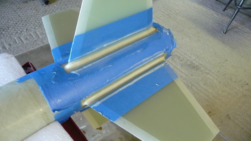
I had to reduce the tang on the stock plastic fins in order to accommodate the larger MMT and the GROOVE-LOK. I used a power miter saw to cut them slightly larger than needed, then fit them with a file. Care must be used not to let the plastic piece get too hot and start to melt – just be patient and take a bit at a time. I bought a 6″ GROOVE-LOK but cut it to fit between the two rear centering rings that encased the fin tangs (picture). The fins were 6-filleted (each side of the fin where it attaches to the motor mount tube, and two both inside and outside on the airframe tube where the fin inserts) with 30-minute epoxy.
I replaced the stock 42″ chute with a 50″ one due to the increased weight of the mods and I used a Nomex® piece in lieu of the baffle that was sent to use with the stock MMT.
The MMT is a phenolic 38mm x 18″ tube from Giant Leap to replace the paper 29mm factory unit. The main coupler (where the payload section joins with the booster section) was replaced with a phenolic one from Giant Leap and epoxied to the booster rather than the sustainer to better protect the booster lip on ejection.
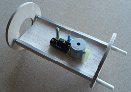
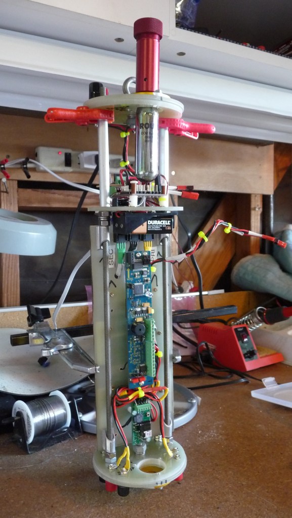
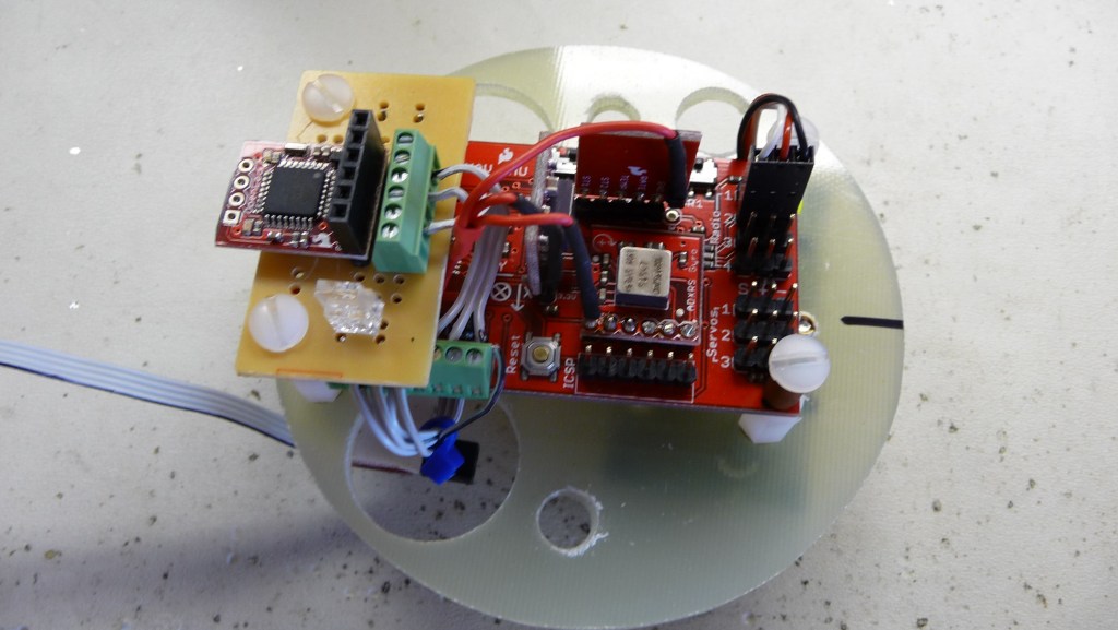
The e-bay was scratch built from a phenolic coupler and plywood bulkheads. The sled (platform where the electronics mount) slides on 8-32 all-thread and is made from 1/8″ balsa plywood and two pieces of aluminum 3/16″ square tubing.
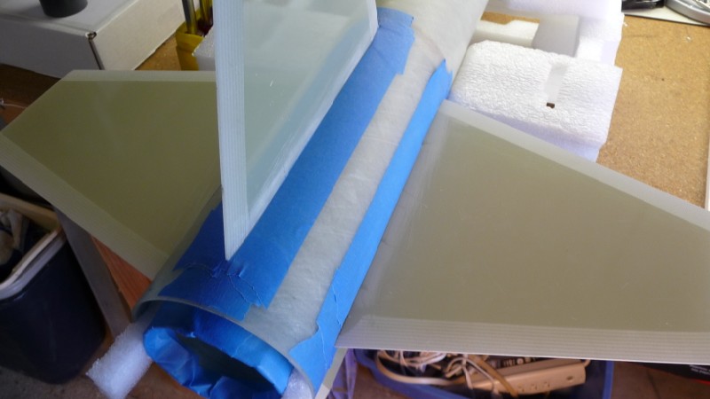
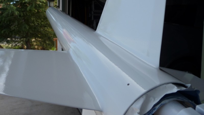
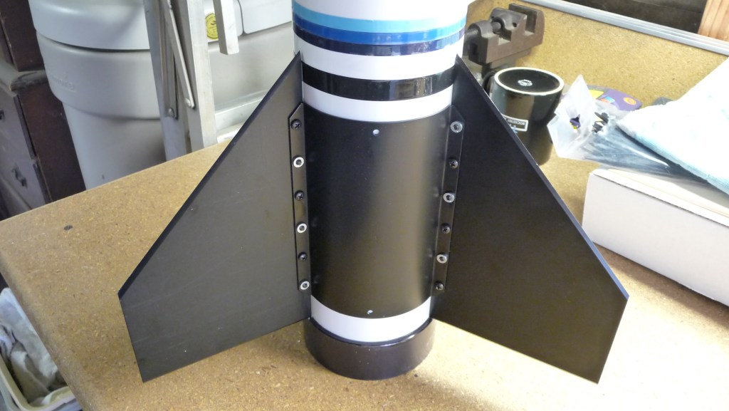
My first fin can…
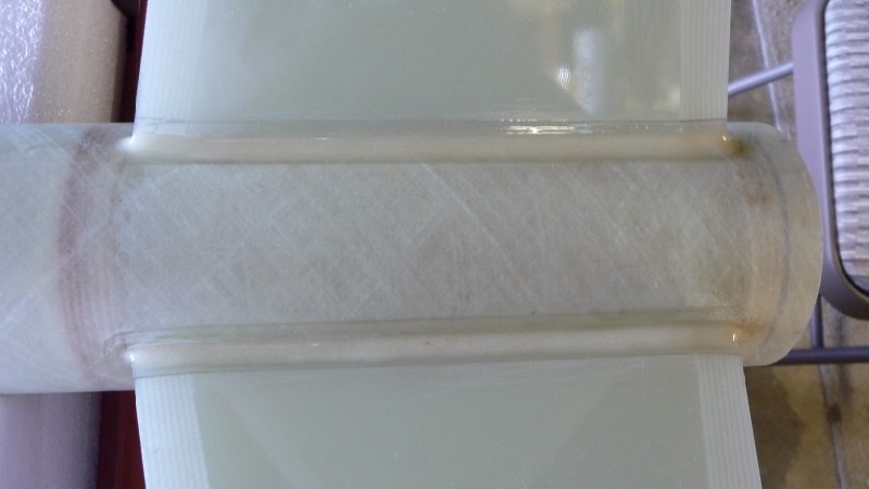
I used the GROOVE-LOK, so that once I set one of the fins in place, the alignment of the others was a snap, plus the individual groove rails gives the fin a nice sturdy mount to complement/strengthen the expoxy fillet. The exterior fin root bulges in the middle making the filleting process a bit more difficult to make it look good, but I had it down by the third fillet.
The overall kit went together easily and the instructions were clear. I filled the airframe tube spirals with Elmers wood filler and acheived a decently smooth exterior with one application and sanding. I did not use the included decals, but rather made my own. The finish was gloss white. Looked really nice sitting on the launch pad.
Flight – The stock kit called for G motors (motors are rated for their total thrust using the alphabet, A being the smallest and going up from there), but going from the 32 oz. stock dry weight to the final 56 oz. for the modified version called for more power. I bought a G38, a G40 and a G77 with the kit before I decided to modify it.
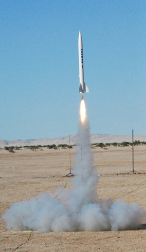
I simulated all of my rocket builds and their flights using a software product called RockSim – it proved over my journey to be a wonderful tool to match motors with different rocket configurations and see how they performed. The G38 and G40 RockSim’d as a crash, whereas it said that the G77 should put it to 400’+, which is what happened.
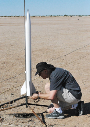
The first flight was on a G77-4 (the digit after the dash indicates how much delay in seconds there will be after the motor burns out before the ejection charges blows the sections apart allowing the recovery chute to come out 0 the target is to have the ejection charge fire right after the rocket reaches apogee to minimize the force on the chute when it opens.
Hermes 1 flew perfectly straight with the motor ejection occurring right at apogee and no roll (turning around the vertical axis) to speak of. The bottom of the booster tube sits about a 1/2″ below the bottom of the fins, so on a perfectly still day like we had, the rocket lands on the tube. It crinkled just a bit on one edge. I saw in an earlier article that someone had reinforced that area with a piece of coupler tube. I intended to do so but forgot – wished I had, but I will reinforce it somehow in the future before it flies again.
On landing, the booster hit on the hard-pack desert road and worstened the crinkle, so I definitely needed to add something there, or, go to my 58″ chute, or, both.
The G-Force is a great flyer as reflected in all the reviews I had read during my research The stock components were very nice as far as quality, but I wanted something a bit stronger in the booster/fin configuration since I planned to eventually see about the rocket going to 5K’ (see Hermes 2 below).
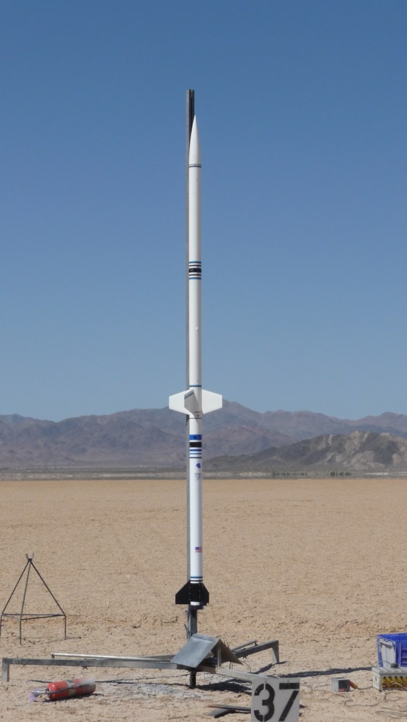
Hermes 2 – a further modified Aerotech G-Force
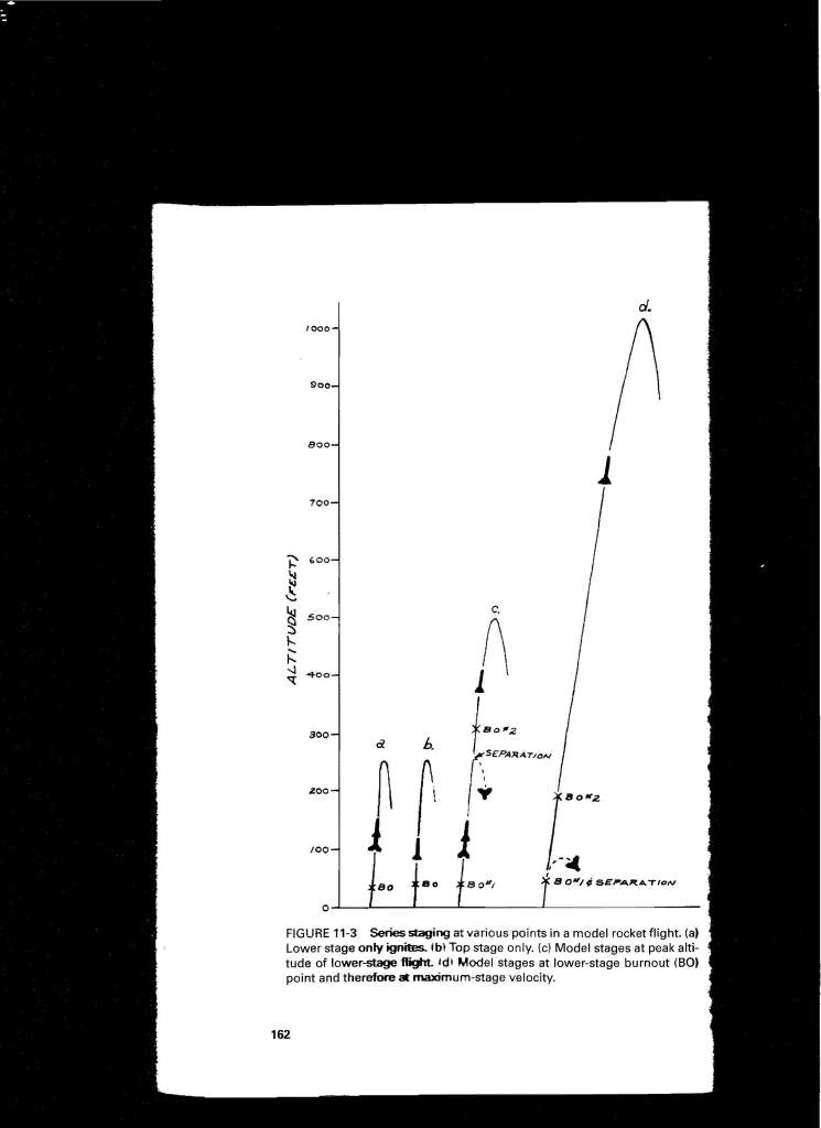
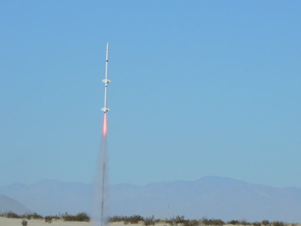
Hermes 2 was used to gain NRA Level 2 certification…it used the basic Hermes 1 components, with the addition of a larger payload section so I could use dual-deploy for recovery – drogue chute in the booster and main chute in the payload – more sophisticated in that it potentially allows the recovery range to be reduced quite a bit for high flights – the drogue goes out at apogee, and since it is small, the rocket returns to earth much more quickly, rather than popping the main chute up there and having the wind carry it far away – the main chute is then deployed relatively low so the drift is minimized – a flight computer (my choice) or timer is used to control those events…also note, this is my first use of CO2 rather than black powder for separation of the sections – much less pollution and mess than using black powder…since this rocket was designed for higher flights, I also added a tracker in the nosecone…
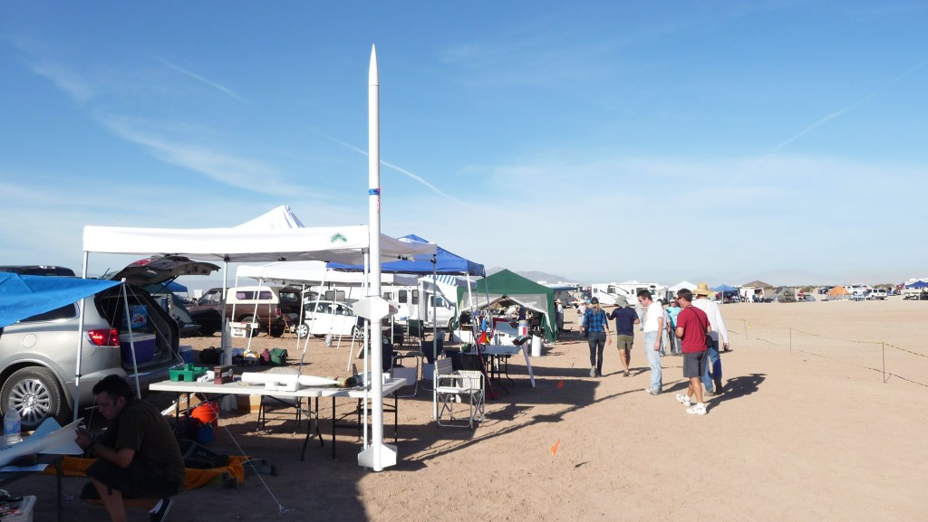
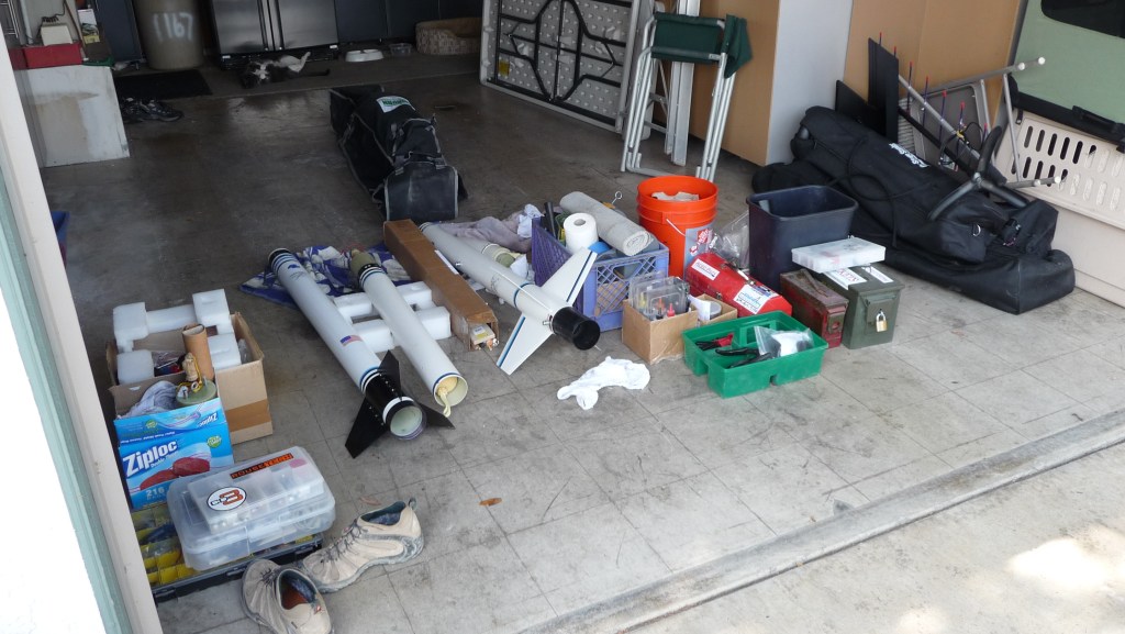
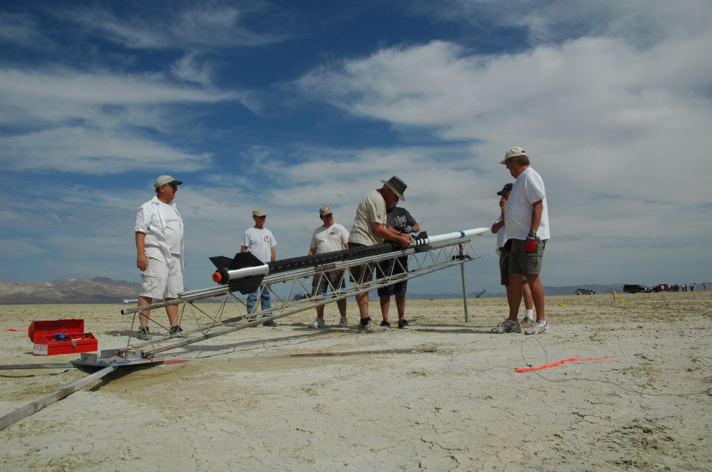
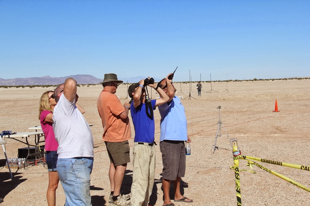
Getting ready…used my AWD drive Buick Enclave for recovery – worked really well in the sandy desert out by Plaster City, CA, which is where the local San Diego club had its launch site…
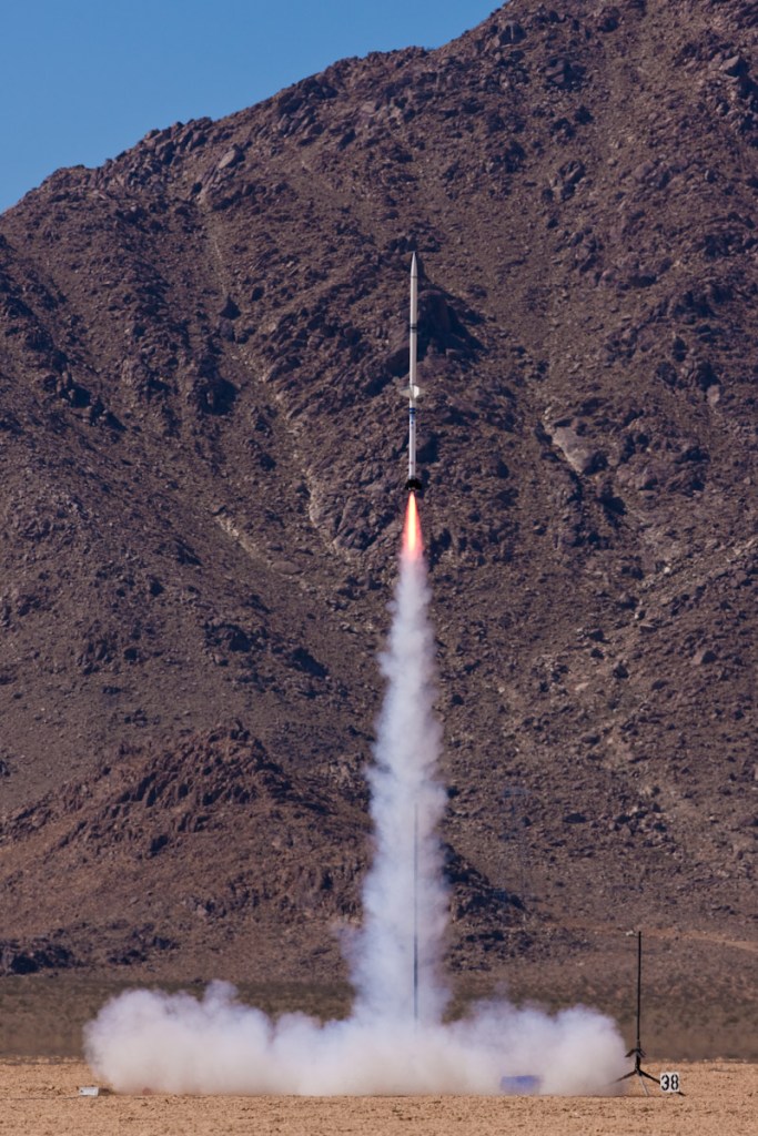
River didn’t think much of the drive out and back from the desert, but loved being there – he was always welcomed by the rocketeers and their friends and family…all the noise and commotion never bothered him – he is a bird dog after all!Early single-stage launch…Electronics bays hold gizmos needed to track flight data and also figure out when to deploy recovery chutes…Computers are used to configure the electronics for each specific flight profile…
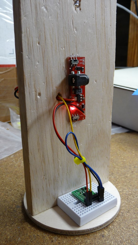
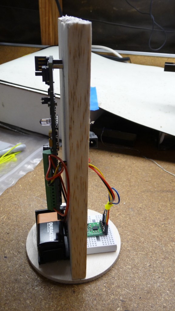
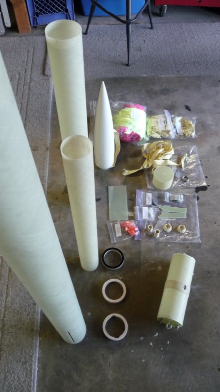
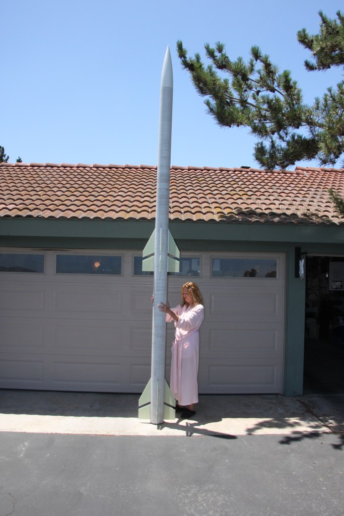
Somewhere early on, though I initially swore I would not build rockets to go high, I decided the complexity of 2-stage rockets would be interesting, which in turn eventually lead to the development of the RockeTiltometer…I built lots of test rigs for that project and flew them for verification…As things progressed and I moved on to bigger-and-better, more powerful rockets, I did not like the fragility of cardboard tubes for rocket bodies, so decided to build a fiberglass kit – Tammy is showing off my first one – intended for my TRA Level 3 qualification project…
Hawk Mountain Enterprises Bad Attitude kit…
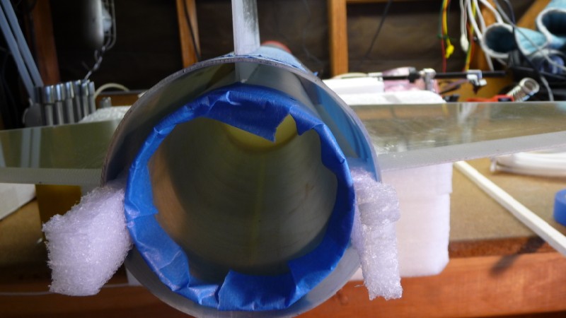
Toughest part of the fiberglass builds, and most high power rockets, is doing the thru-wall fins and their respective fillets where they met the body…one thing I did was to design a fixture to help align the fins…Ahhh – mission accomplished!
Got my TRA Level 3 out at the Lucerne Valley site (Plaster City kept high-winding out)…
Custom aluminum inter-stage coupler I had made up – starting with a piece of tube, I had it machined to an O.D. that mated to the inside of the fiberglass tube and an I.D. that allowed the motor to pass up to the motor retainer inside the fin can… Per my original plans for the fiberglass rocket, I soon added some sections and converted it to a 2-stage…I had designed and built the RockeTiltometer by this time so it was along for the ride and worked well to air-start the second stage, as well as act as an adverse flight-angle abort mechanism…
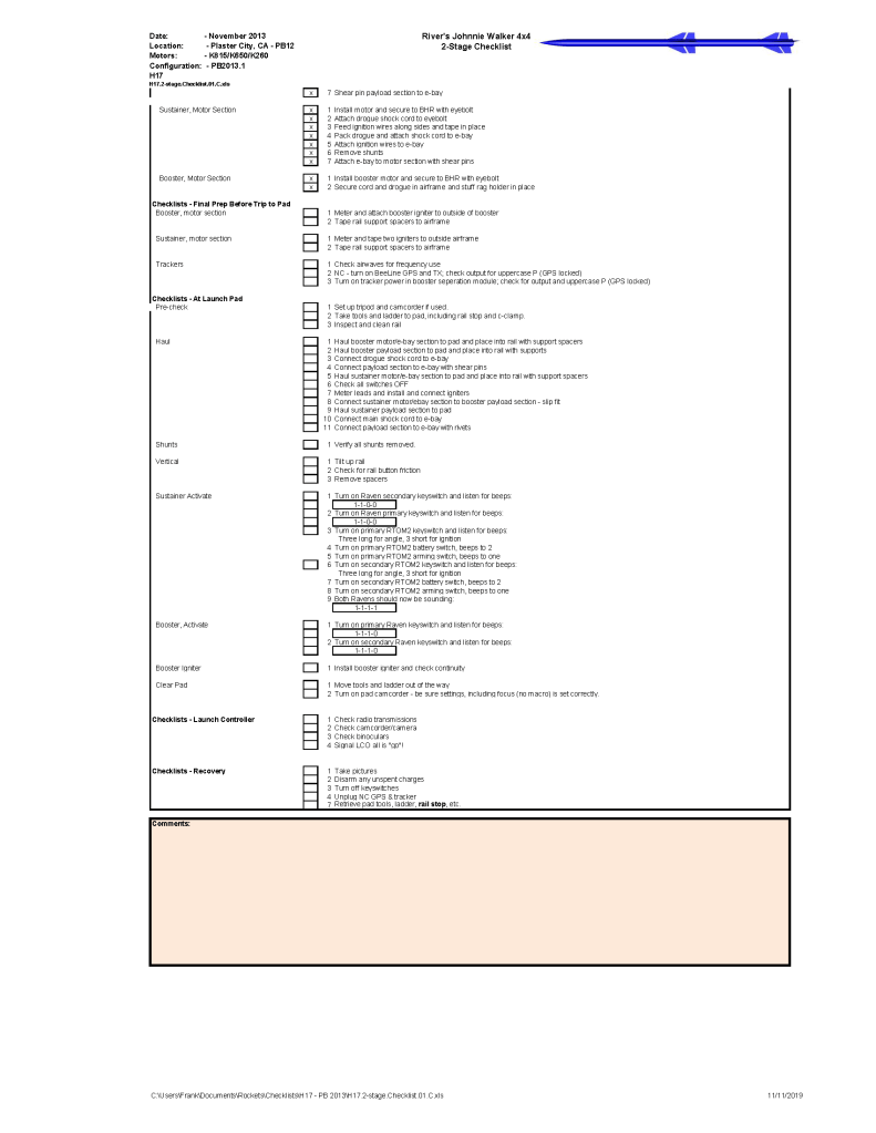
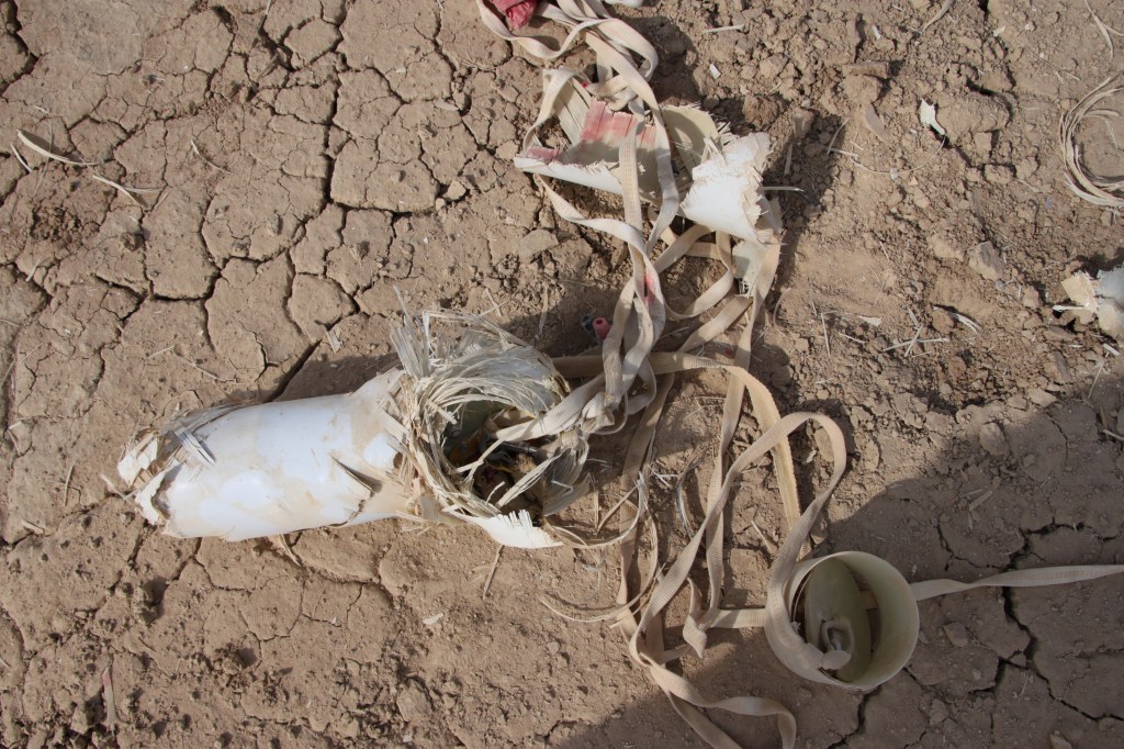
Some of the rocket staging and recovery configurations can get a bit complicated!Fortunately, there is software available, RockSim in this case, to simulate flight and recovery – an invaluable tool when you get into high-powered, high-altitude, staged rocketry… Since many of my flights were pretty complicated, I created checklists to be sure I did all the required steps to engineer, configure, prepare, and launch the rockets safely – most of the time, things worked – sometimes, not… Uh, oh…Even with lots of planning, high-power rockets can bite you in the ass…it can get to be a pretty expensive hobby! After a few mishaps, I thought it might be easier to build my rockets using aluminum fin cans that bolt on, rather than doing the thru-wall, filleted fiberglass fins… Getting ready to head out to a launch…
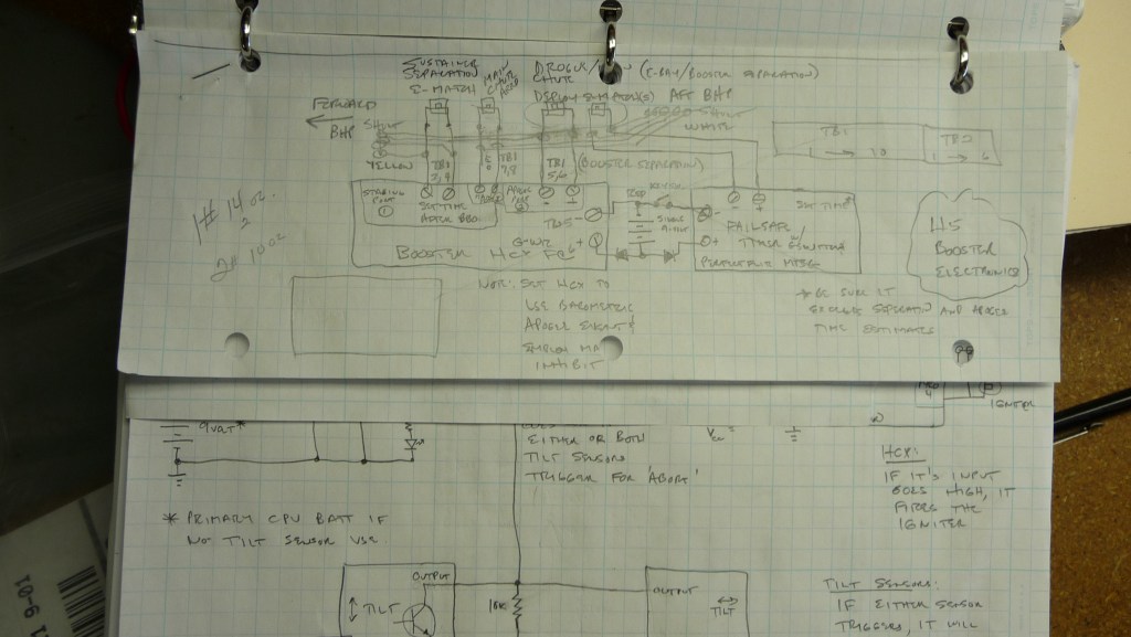
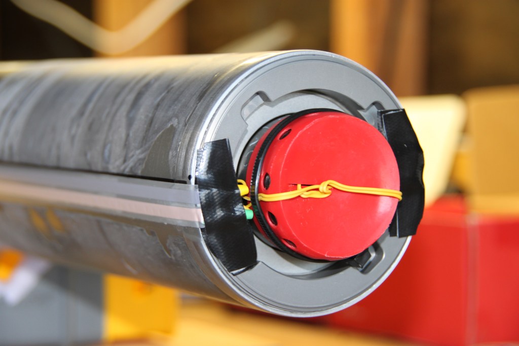
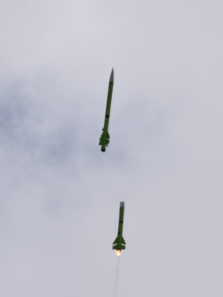
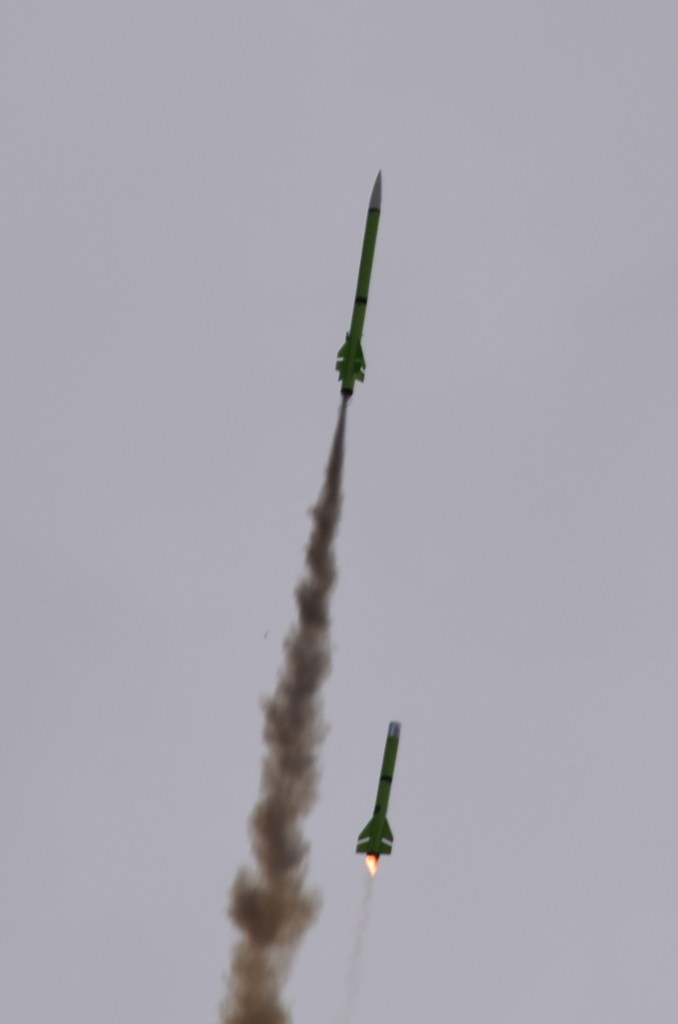
2-stage electronics with GPS recovery for both stages and a CO2 bulkhead to cause the booster to separate from the sustainer at a pre-determined staging interval…
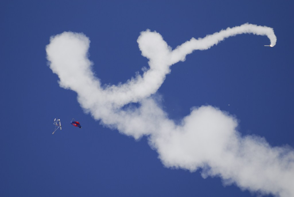
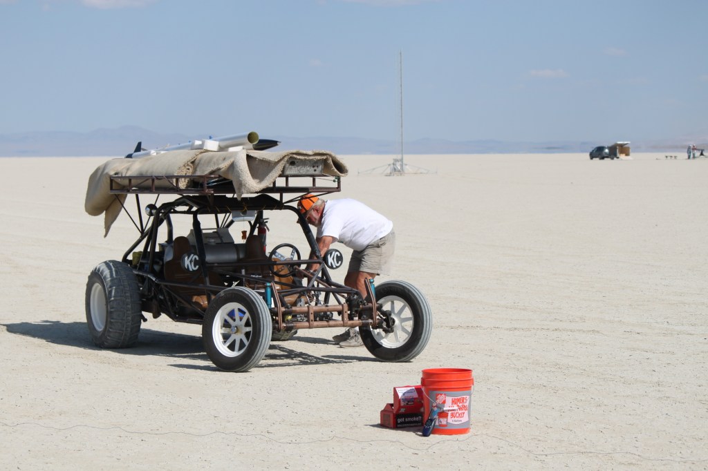
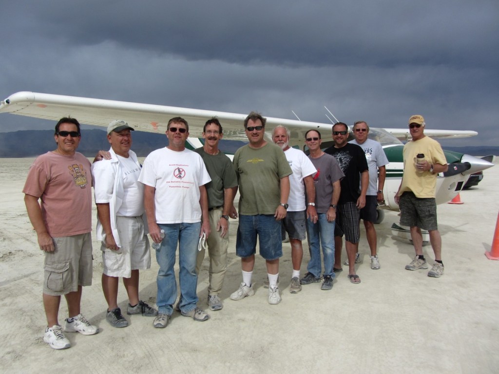
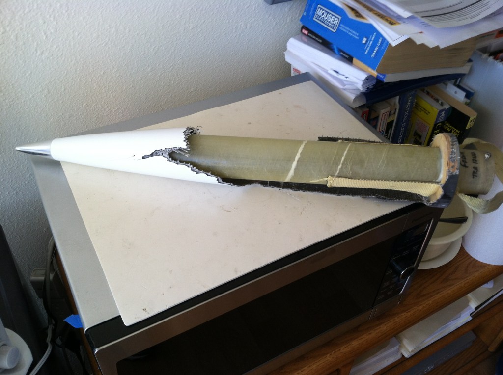
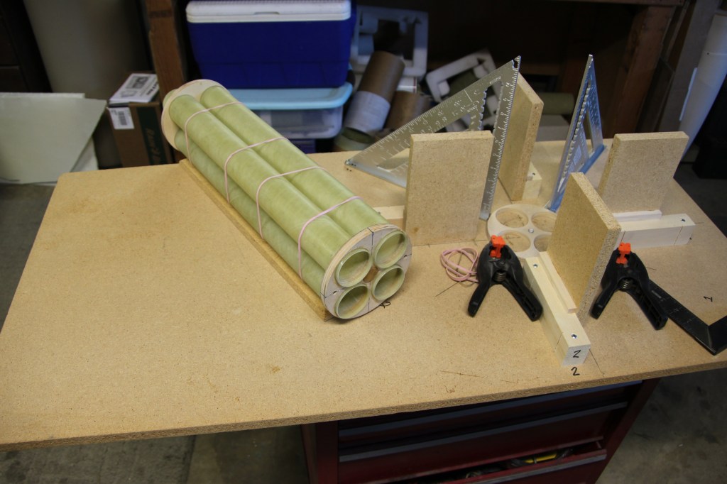
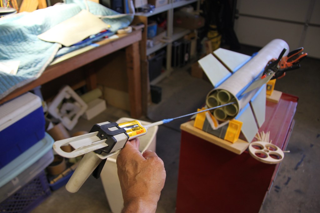
With GPS transmitters installed in the electronics bays, you can track the flight of the rocket (interesting to see the post-flight profile data overlaid on Google Earth) to aid in recovery…the transmitters in the rocket continue to send out their position during and after flight, allowing hand-held receivers to track and lead you toward the downed rocket…one year, at the annual San Diego TRA Club Plaster Blaster event out near El Centro, CA, twice on successive days, I recovered my rocket almost 8 miles away from the launch site – each time, the big main parachute, designed to open when the rocket gets about 1,000 feet above the desert floor, opened near apogee about 25,000′ up…the winds aloft blew the rockets quite a ways down range…without GPS on board, I could never have found those rockets…got’em both back – fully intact!!Nice to have a buggy available for those long recovery trips…this is Don, my former business partner, who came up to Black Rock desert with his wife Joyce a few times to help out at the BALLS events…Interstage coupler design sketch for machining the motor casing below – true minimum diameter rocket!Cramming as much motor as you can into the rocket body can get pretty tricky at times – here I used doll-house electrical tape along the side of the motor to get the ignition wires down to the rear of the motor from the electronics bay…Mark is the guy that got me started in all this rocket stuff…when I went out to my first visit to the local San Diego site at Plaster City, I witnessed a great Level 3 attempt flight by Mark – I had no idea you could built such great projects – I was hooked…Mark remained my most trusted confidant with regards to high-power model rocket science and he helped me with many of the aspects incorporated in my projects – it was always great to have Mark available to advise and help me think through things – many thanks Mark!Greg was another trusted fellow model rocket guy…very thoughtful with lots of experience and a very willing hand along the way…Greg is also an outstanding, well-respected photographer who records many of the events…Higher and higher…with ceilings limited to 25,000′ locally in the San Diego and Los Angeles area, when you want to go really high, you head to the Black Rock (same place where Burning Man is held) desert north of Reno/Tahoe – there, the ceilings are virtually unlimited as long as you get permission from the FAA…The crew up at Black Rock…The delicate part of connecting the motor igniters to the launch controller…After two attempts to harness the power of the N-5800 motor in the booster, I decided to try using a carbon-fiber body tube – in each of the prior attempts, the force of the motor was so great that the fiberglass booster motor tubes broke in half…Finally got a successful launch, and the rocket staged after an 11-second staging interval (time between when the booster motor burns out and the second stage motor ignites) – the flight simulation software was predicting apogee close to 70,000’…Unfortunately, as the rocket was approaching 30,000′ and traveling almost 2,000 MPH (nearing Mach 3) – the forces on the nosecone caused it to collapse, making the rocket aerodynamically unstable and turning it into a skywriting machine…After chasing adventure up in the desert at Black Rock, I decided to bring things back to San Diego…I wanted a rocket that would provide a lot of interest, primarily for the big annual meet of the local San Diego club…I built a custom 2-stage rocket with the capability of putting 4 motors in the booster section and 4 in the payload section – I called it River’s Johnnie Walker 4X4 in honor of my dog, and my favorite beverage…Tool to inject epoxy for the interior fin fillets…Tammy showing off the finished 6″ diameter rocket prior to painting…Having a total of 8 motors gives lots of options for propellant type – you can change thrust curves, color, etc…here, the main booster had 2 smokey motors and 2 white…the smokeys quit before the whites which are nearing the end of their burn…Staging has occurred due to gravity (no shear pins in the coupler…the main booster motors have almost finished burning and the main booster is dropping away…there is a programmed delay before the payload booster motors will ignite…4 RockeTiltometers are monitoring the payload section to be sure the rocket is flying basically up, else they will inhibit ignition of the payload booster motors…The RockeTiltometers sensed that things were OK, so they allowed all 4 of the payload smokey booster motors to ignite…River’s Johnnie Walker 4X4 soaring away…Another great, stylized photo by Greg – thanks for all your help over the years, buddy!!
Having decided that my semi-retirement was not casting off enough cash to continue my multi-stage, high-power rocketry pursuits, I constructed and flew a few “daily-driver” rockets over the next few years and flew them at the monthly club gatherings.
The rocket club decided to have a “creative” rocket contest at its big annual launch – Holtville Havoc. At first glance, I was not too inclined to participate since most of my rocketry journeys had involved pretty straight-forward high-altitude, staged rockets. They were innovative and complicated rockets, but not what I would have called creative. Creative to me were such projects as flying beer kegs, ultra-lightweight affairs, tube rockets and the like. One day, I re-thought things.
One of the events at the annual launch is a night launch. When I was developing my interactive, voice-controlled robot, Jarvis (see elsewhere on this web site), I used an LED matrix to give it a face on which I displayed pixel maps so he could smile, frown and wink. I had also used such individually addressable LEDs on a marble maze project I built for my grandson to give it some additional animation and color.
I decided to try and develop an LED strip-based matrix in a clear tube that could display different patterns dependent upon its flight state, i.e., a pattern during launch, switching to another at apogee for the drogue chute, another at main chute deployment, and finally, one after landing to help in recovery in the dark. I would insert his tube into my 75mm daily-driver rocket and have some fun night flying at the Holtville Havoc. This is a video of the tube construction…
This video shows the various displays a bit better than the one above…